This is an update of the 606 Bass Drum clone: version 1.2
Addition of an op-amp buffer output and correction of the trigger circuit (PNP instead of NPN for Q2)
How it works
The 606 Bass Drum uses a double Twin T damped oscillator. Each oscillator is tuned to a different frequency. The output of each oscillator is mixed together and the “Tone” potentiometer sets the amount of signal from each oscillator to be fed to the output buffer.
The output buffer amplifies the signal to Eurorack compatible levels (+10/-10Vpp).
The input is common for both oscillators.
The input circuitry converts any Gate signal and negative excursions into Trig signal.
The Accent potentiometer and its associated input jack allow you to change the volume. If the jack connector is plugged, the potentiometer is bypassed.
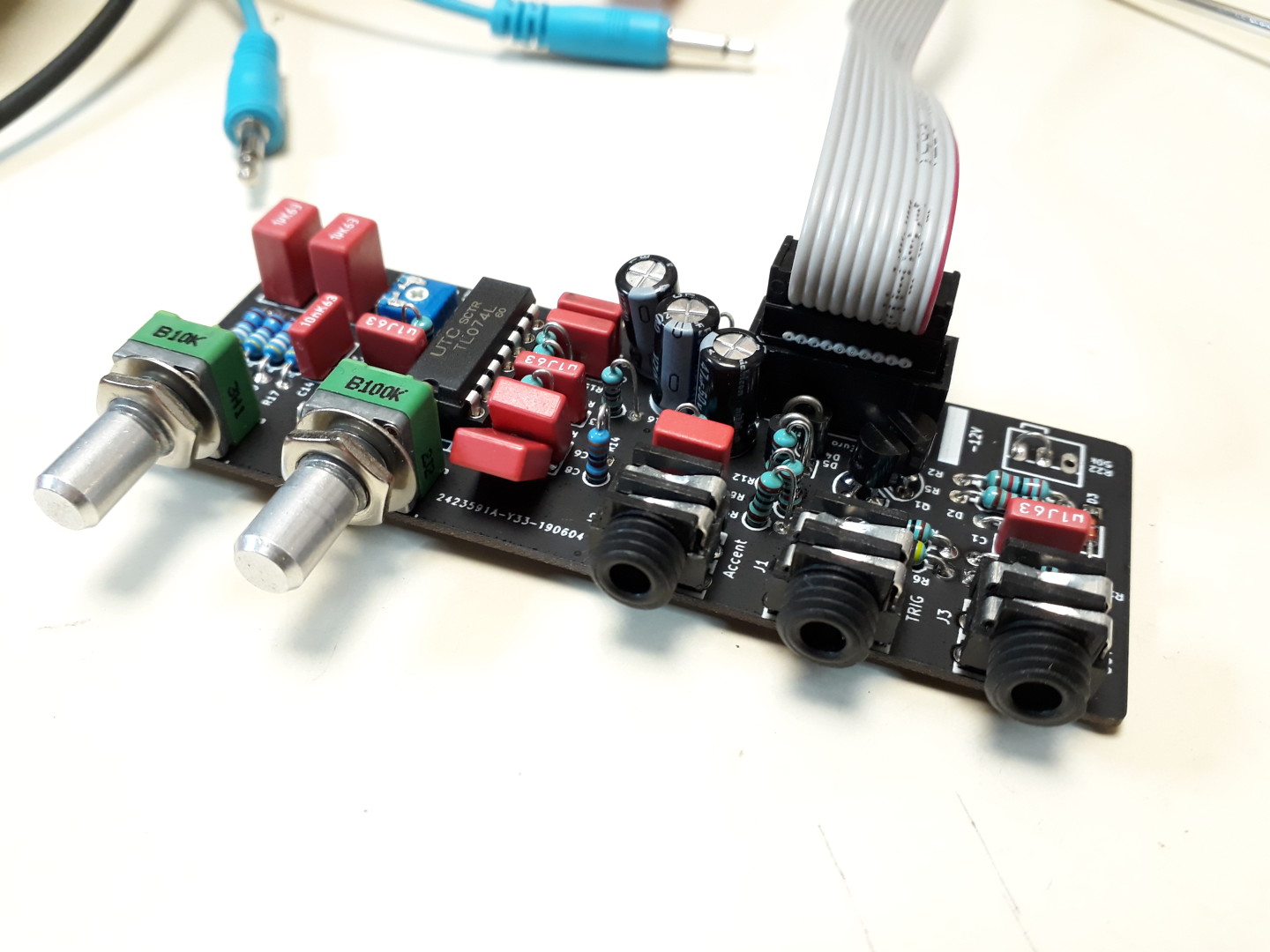
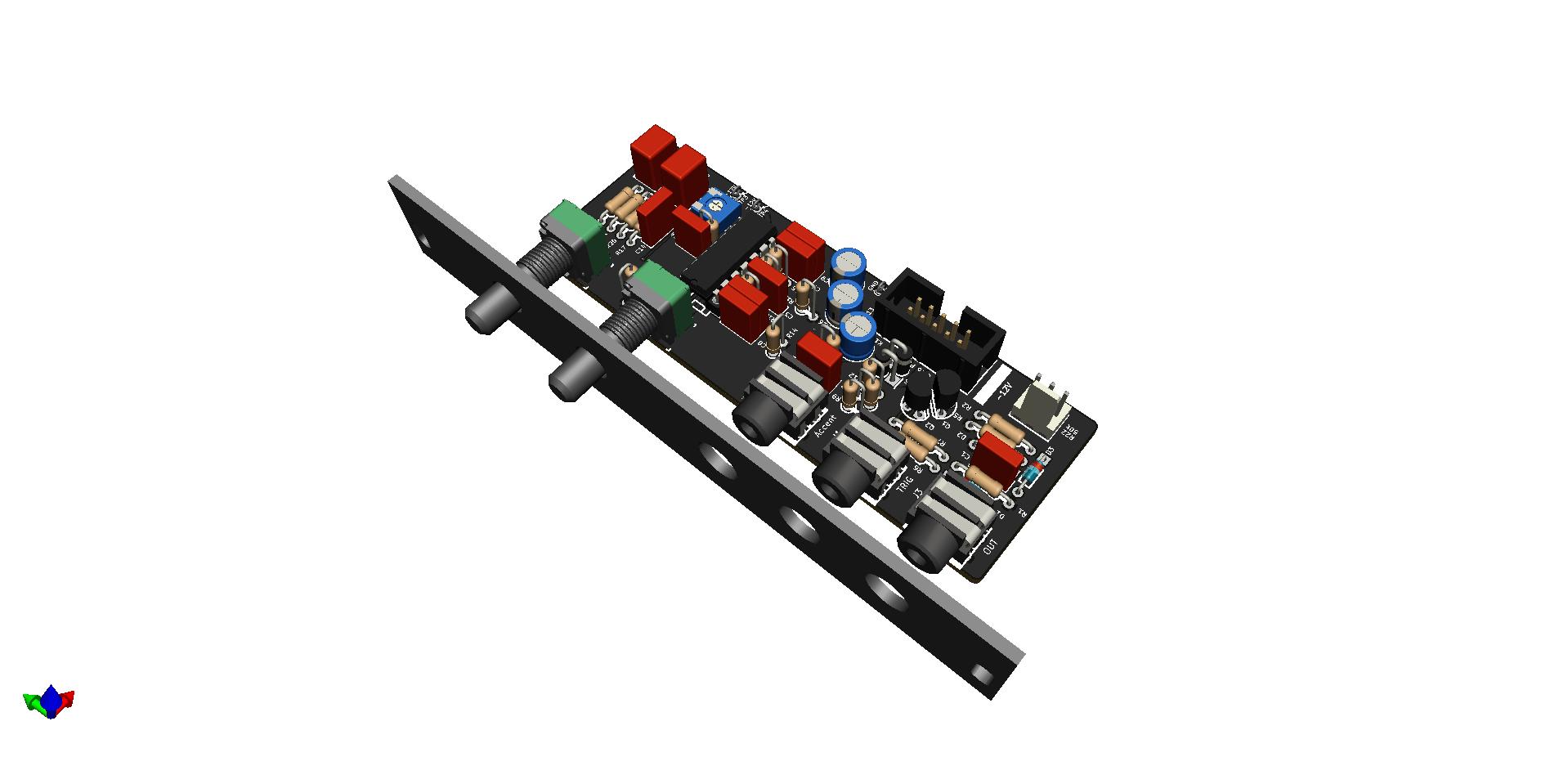
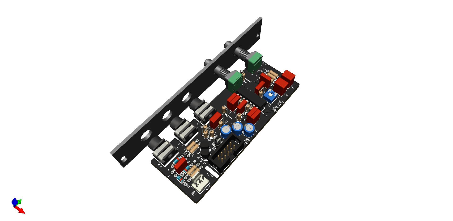
Gallery
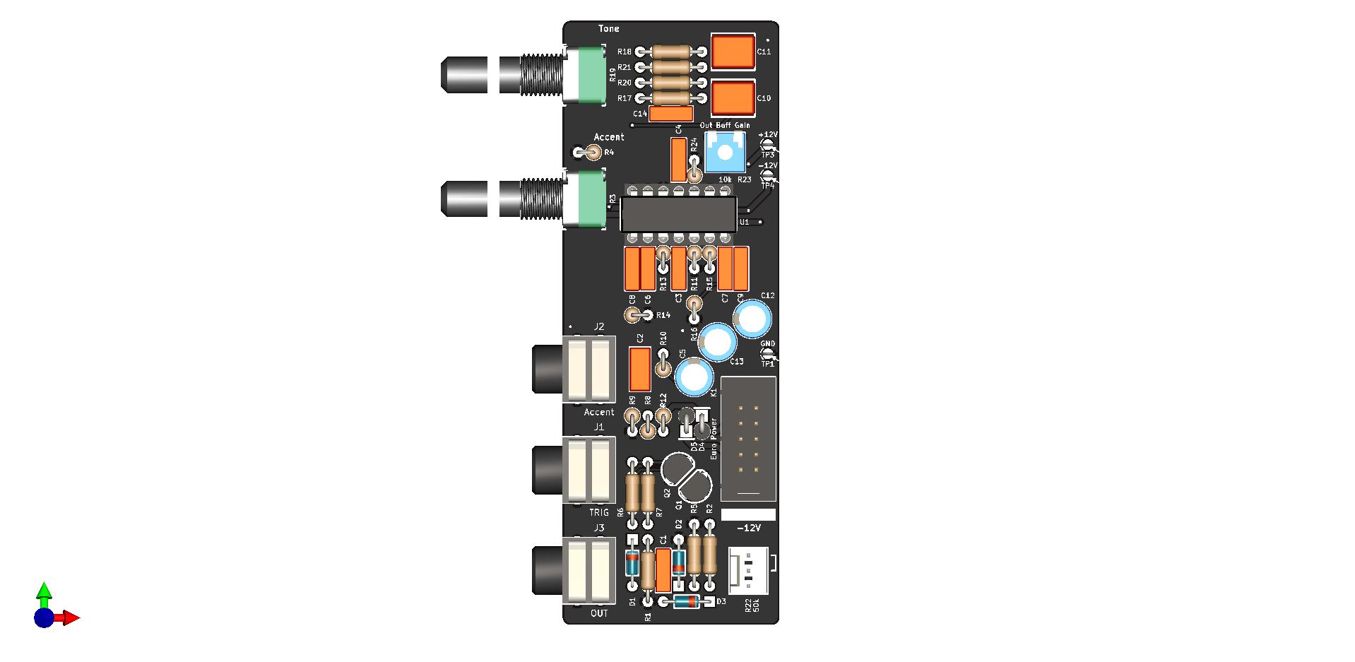
The output buffer has a trimmer potentiometer (R23) for setting the output amplitude. Turn Clock Wise to increase the output, CCW to decrease. Adjust until distortion disappear (the maximum amplitude is when “Tone” potentiometer is set on middle position).
Build instructions
The build process is straightforward. I recommend to refer to the Interactive BOM. The interactive BOM doesn’t represent the components in a particular order.
It’s easier to start by soldering the smaller parts (diodes, resistors) first and finish with the bigger ones (capacitors, etc).
I also recommend to first tighten the jacks and the potentiometers to the front panel before soldering them.
Most of the components values are written down on the silkscreen. Those values are, to date, correct.
Some resistors are mounted either horizontally or vertically. There’s no polarity to respect.
The diodes are polarized. Please follow the silkscreen marks.
Diodes D4 and D5 can be omitted and replaced by simple jumper wires, but they help protect your module against reversed power supply.
They are mounted vertically. The cathode (the white ring) is up.
Salut, j’ai chopé le PCB version 1.3 mais ni la BOM ni le schéma ne correspond niveau composants. j’ai pas eu trop de mal à retrouver la plupart des références, mais je sèche sur le condensateur C5 qui est à la sorte du Buffer en parallèle du trimer R23 (j’imagine que c’est une petite valeur pour faire une LP en sortie).
Autre question, si Q2 est changé pour un BC547, est ce qu’il faut faire une manip sur le PCB ou c’est déjà changé ?
Merci pour les réponses.