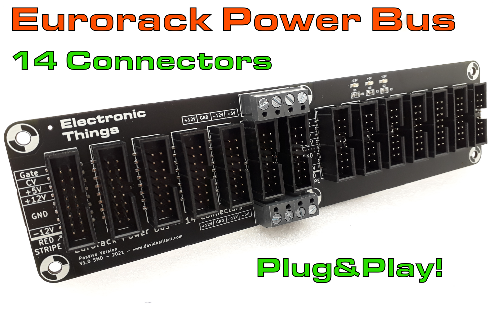
The Eurorack Power Bus – 14 is available in pre-assembled SMD version.
Category Archives: Eurorack Power Buses
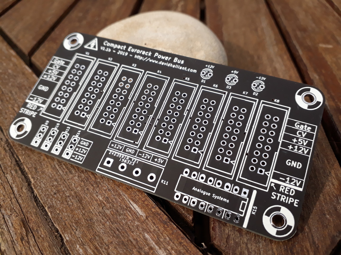
Eurorack Compact Power Bus – Version 1.1d
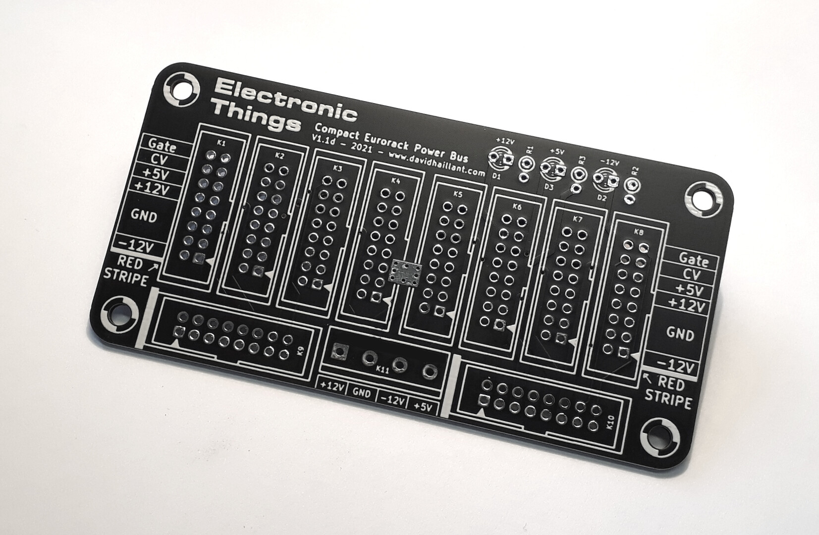
New revision for the Eurorack Compact Power Bus!
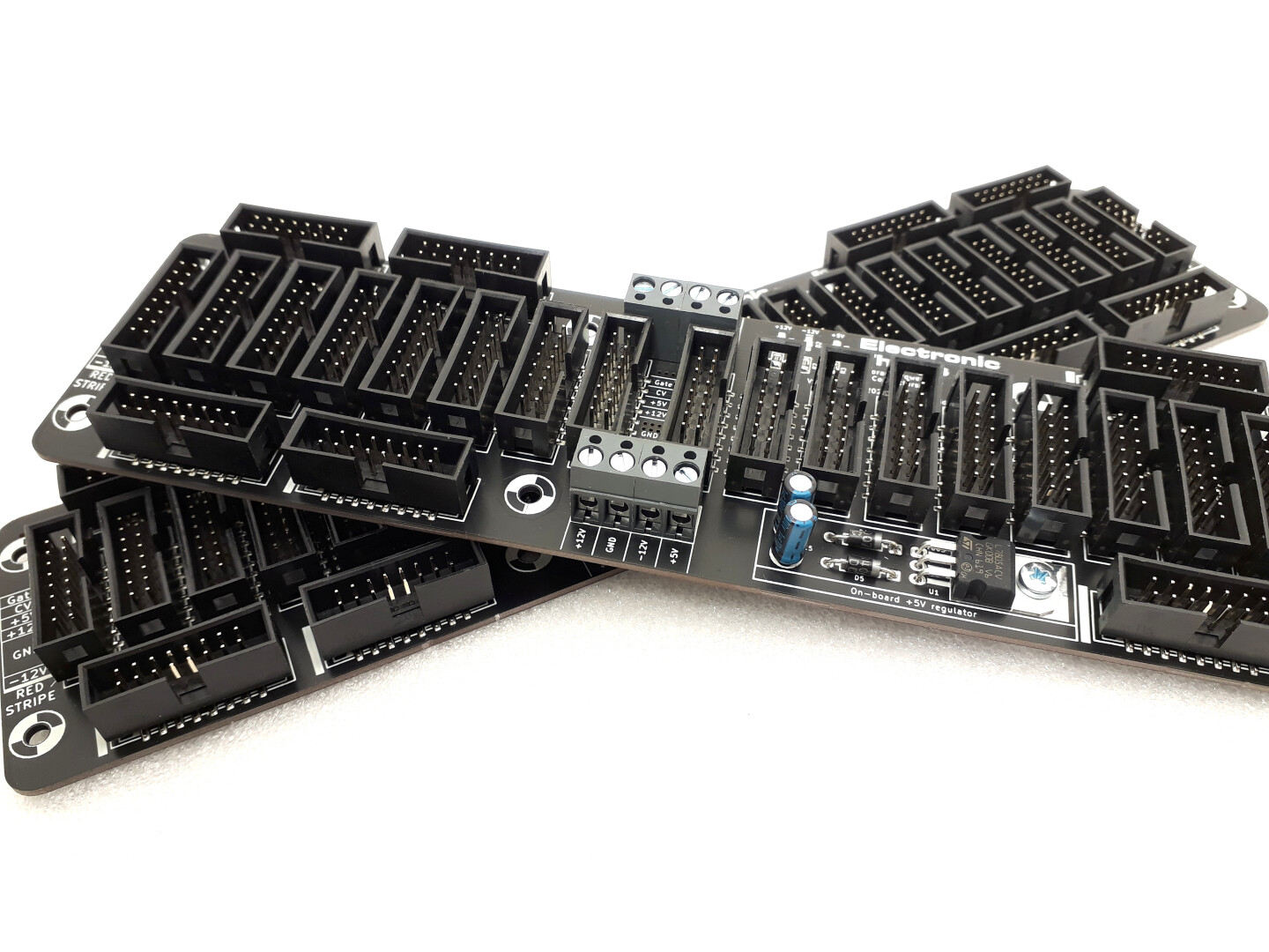
Bus Comparison Guide
Feeling a bit lost with all the different Eurorack Buses? Here is a list and a summary of the various versions available.
Eurorack Power Bus – 28 Connectors
This is the biggest Eurorack Power Bus: 28 connectors on a 25cm x 6cm board!
Continue reading Eurorack Power Bus – 28 Connectors
Eurorack Power Bus – 18 Connectors
The Bus number 18 is here!

Continue reading Eurorack Power Bus – 18 Connectors
Eurorack Power Bus – 26 Connectors
This is the Eurorack Power Bus on steroids: 26 connectors on a 25cm x 5cm board!
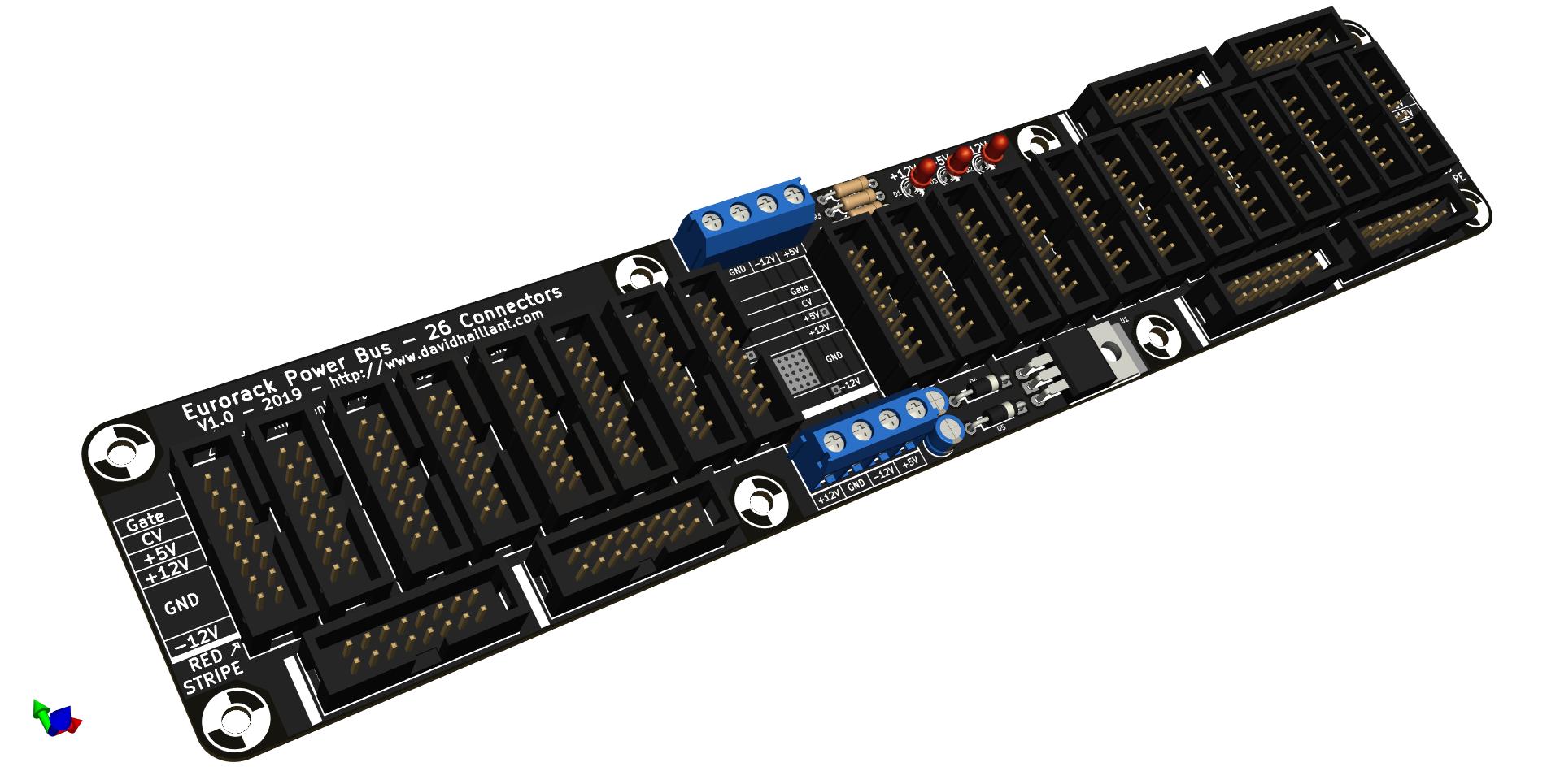
Continue reading Eurorack Power Bus – 26 Connectors
Eurorack Power Bus – 14 – Update 1.1

The Eurorack Power Bus with its 14 Euro connectors is back in an updated version.
Continue reading Eurorack Power Bus – 14 – Update 1.1
Eurorack Compact Power Bus – version 1.1b B(L)ACK in stock
New revision for the Eurorack Compact Power Bus!
Continue reading Eurorack Compact Power Bus – version 1.1b B(L)ACK in stock
Compact Eurorack Power Bus Version 1.1
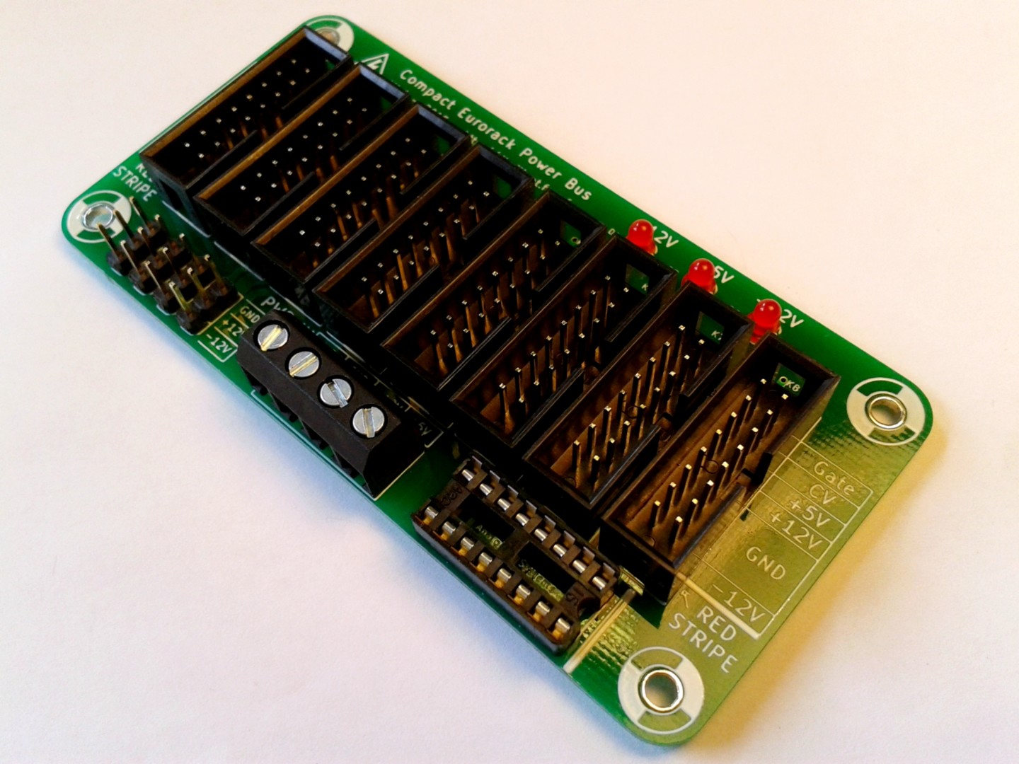
It is time for an update of the Compact Eurorack Power Bus! This is version 1.1!
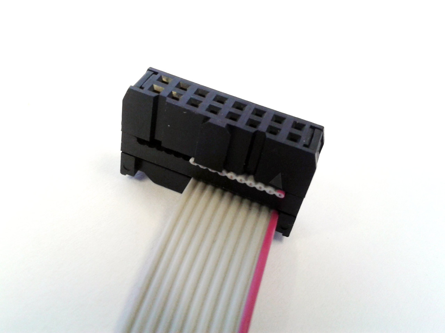
How to link 16 pin Eurorack Power Connector to 10 pin Connector
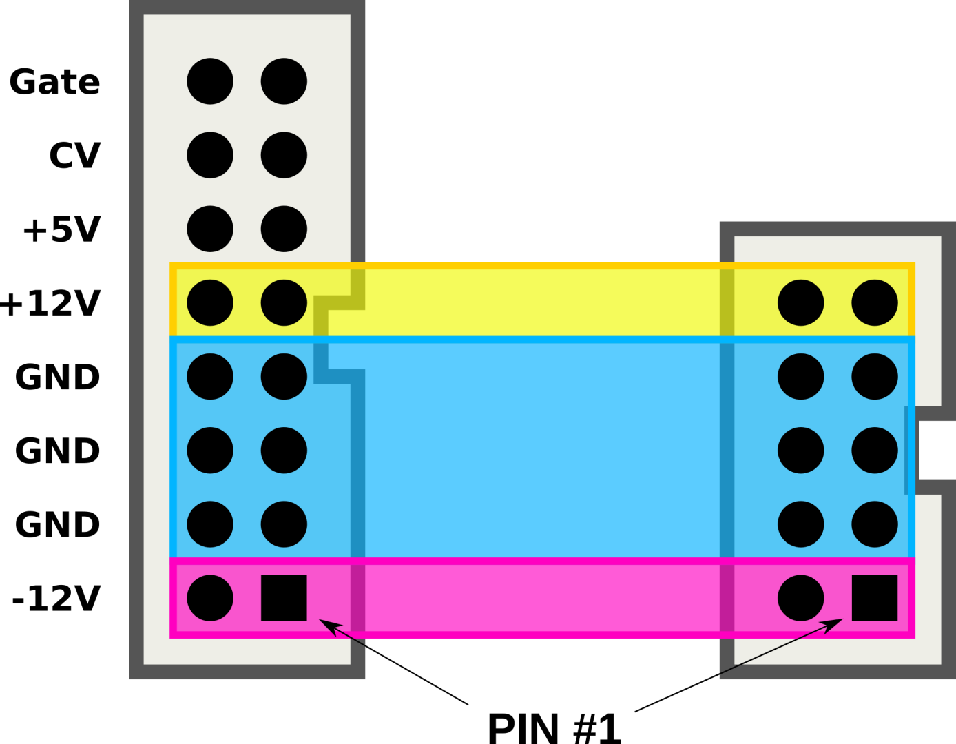
Usually, the pin #1 of a ribbon is colored in red or blue. Never trust the ribbon cable color! And never trust a cable.
Always check twice the correct polarity and voltage before pluging your module!