Your Eurorack Chromatic Tuner utility.

Tuner is an extremely useful tool, and should be installed in any system: It will help you keep your VCOs in-tune with other oscillators, or with the other players in your band.
Tuner is based on the sub-circuit proposed by LMNC in his amazing Performance VCO.
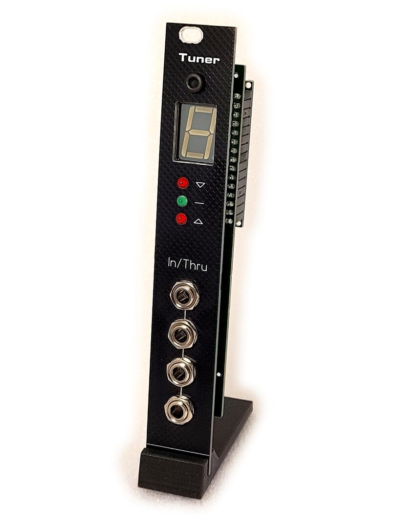
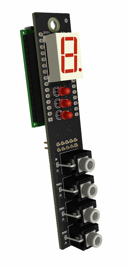
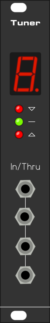
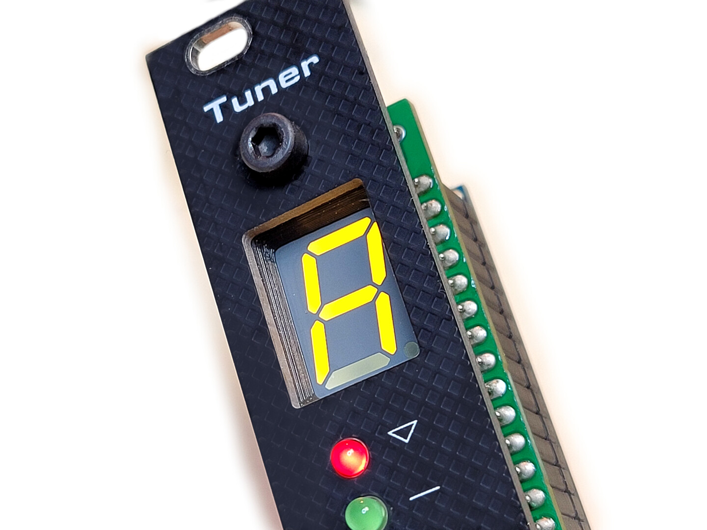
The 7-segment LED display shows the current note detected. The note is displayed as A b C d E F g, and the sharps are indicated by the dot in the lower right corner (example, “A.” represents the note A#).
The three LEDs below the display indicate if the displayed note is in-tune (within a certain percentage) or not.
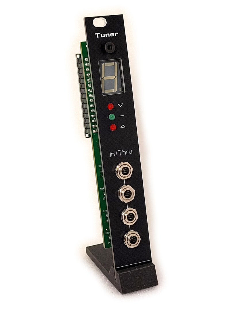
Also, the module is equipped with 4 input jack sockets, offering a passive multiple. You have the possibility to input your oscillator’s signal into any of the 4 sockets, monitor the tuning, and subsequently route your signal to connect with other modules as needed.
Circuit description
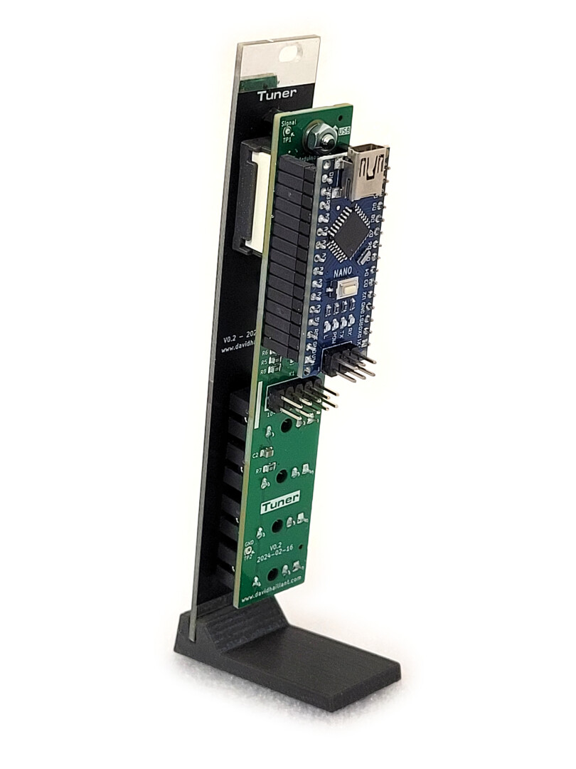
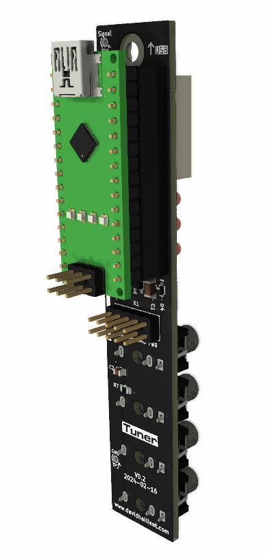
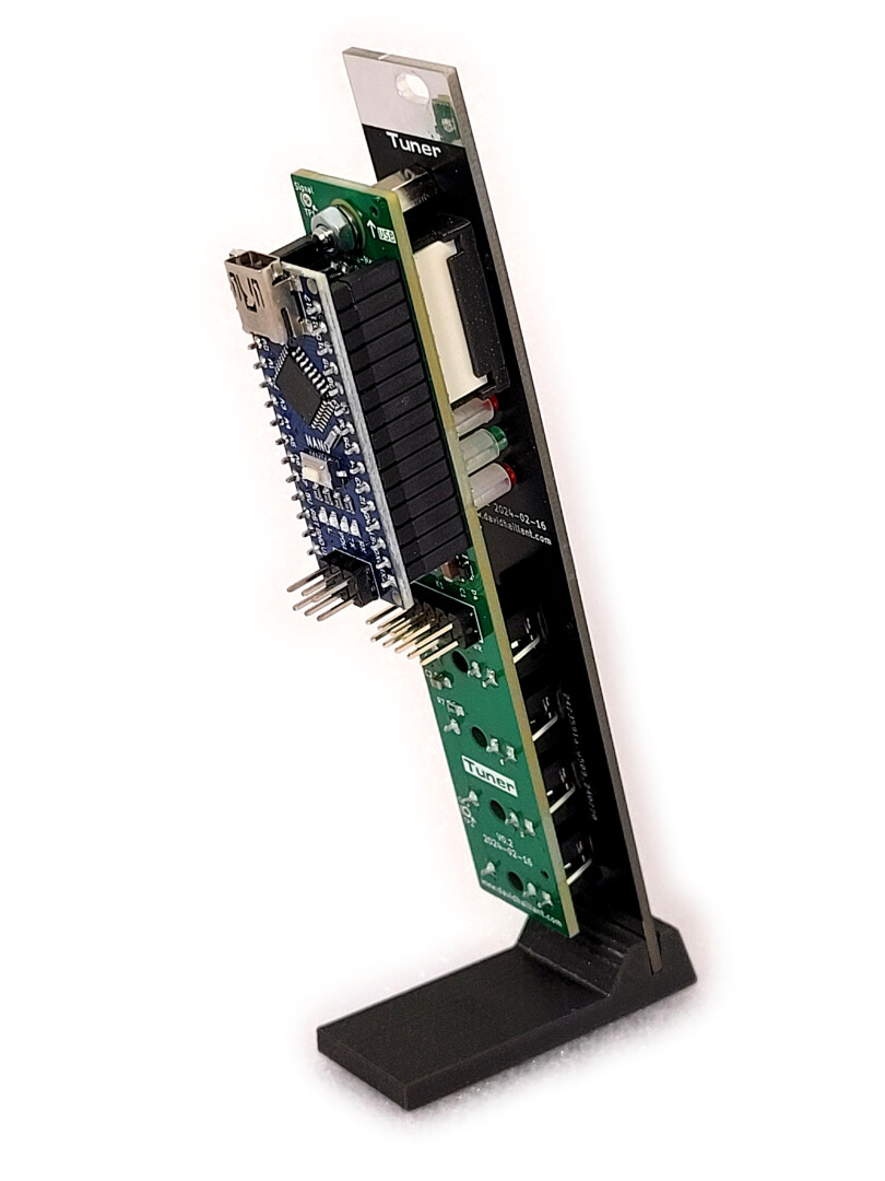
The circuit is relatively simple, featuring an Arduino Nano as the module’s core, along with input jacks, three indicator LEDs, and a single 7-segment display.
The Arduino Nano does all the hard work: it samples an analog signal, tries to detect the rising edges, measures the time between each cycle, averages the values, converts the result to a frequency, compares that frequency to a table of frequencies/notes pairs and finally displays the corresponding note. Additionally, it indicates whether the note is above, below, or in-tune.
The circuit is powered by a 10-pin “Eurorack” connector. Only the +12V rail is used here, and the +5V is derived from it by the Arduino on-board regulator.
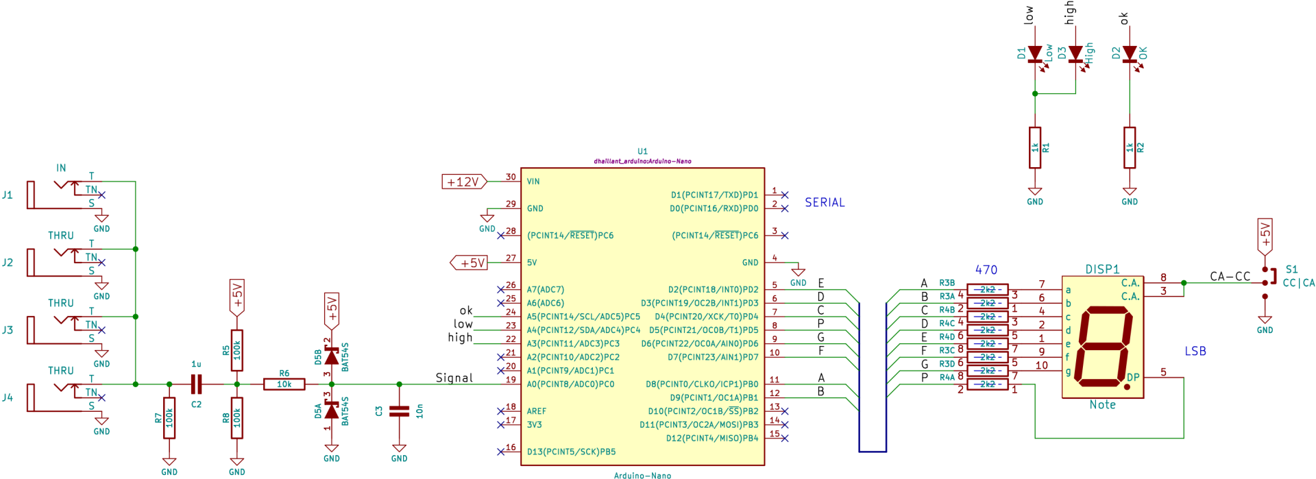
The Arduino ADC input is AC-coupled and DC biased at Vcc/2. Two clipping diodes protect the ADC circuitry from excessive voltages.
The 7 segment display can be either Common Cathode (CC) or Common Anode (CA) and the jumper S1 selects which type of display is installed.
The 4 jack sockets are passively connected. This way, you can insert your signal on any connector, and get 3 (passive) outputs. So, even if you don’t use the tuner feature, the module can still be used as a 1-to-3 passive multiple.
Components
Most of the components are in Surface Mount Technology (SMT) and are already soldered. The only components you need to solder are the Through Hole ones.
Arduino Nano and sockets
Aliexpress links:
7-segment LED Display
Dimensions:
- Character size: Approximately 13.2 mm (0.52″).
- Module size (W x H x T): Approximately 12.4 mm x 17.5 mm x 7 mm.
- Footprint (“Package” or “Case”): Often referred to as “10-DIP” (0.600″, 15.24 mm).
Parameters to choose from:
- Color: Depends on your preferences.
- Brightness (in mcd):
- Low brightness: May be difficult to read in daylight conditions.
- High brightness: Can be overly bright, especially for red displays, and hard to read in low-light environments. However, you can reduce the intensity using a PWM setting in the software.
Common Anode vs. Common Cathode:
The choice doesn’t matter much as it can (and must) be configured in both hardware and software.
Compatible displays:
I like to use the Kingbright SA52 series (or SC52 for Common Cathode variants):
- SA52-11GWA (Mouser No: 604-SA52-11GWA or DigiKey Part Number: 754-2282-ND),
- SA52-11EWA (Mouser No: 604-SA52-11EWA, DigiKey Part Number: 754-2281-ND),
- SA52-11SURKWA (Mouser No: 604-SA5211SURKWA, DigiKey Part Number: SA52-11SURKWA-ND)
The first two are slightly dim unfortunately.
Vishay TDS series (not tested) seems to have a lot of choice with the TDSO5150, TDSO5160, TDSG5150, TDSG5160 series. (Mouser No: 78-TDSG5150-MN, 78-TDSG5150-N, 78-TDSG5160 etc)
Vishay Displays
Broadcom HDSP-561E should fit too (DigiKey Part Number: 516-4238-ND)
Additional resources:
You can also refer to the various links and information on the page Components and parts.
Assembly
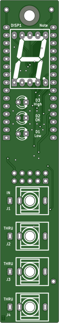
LEDs
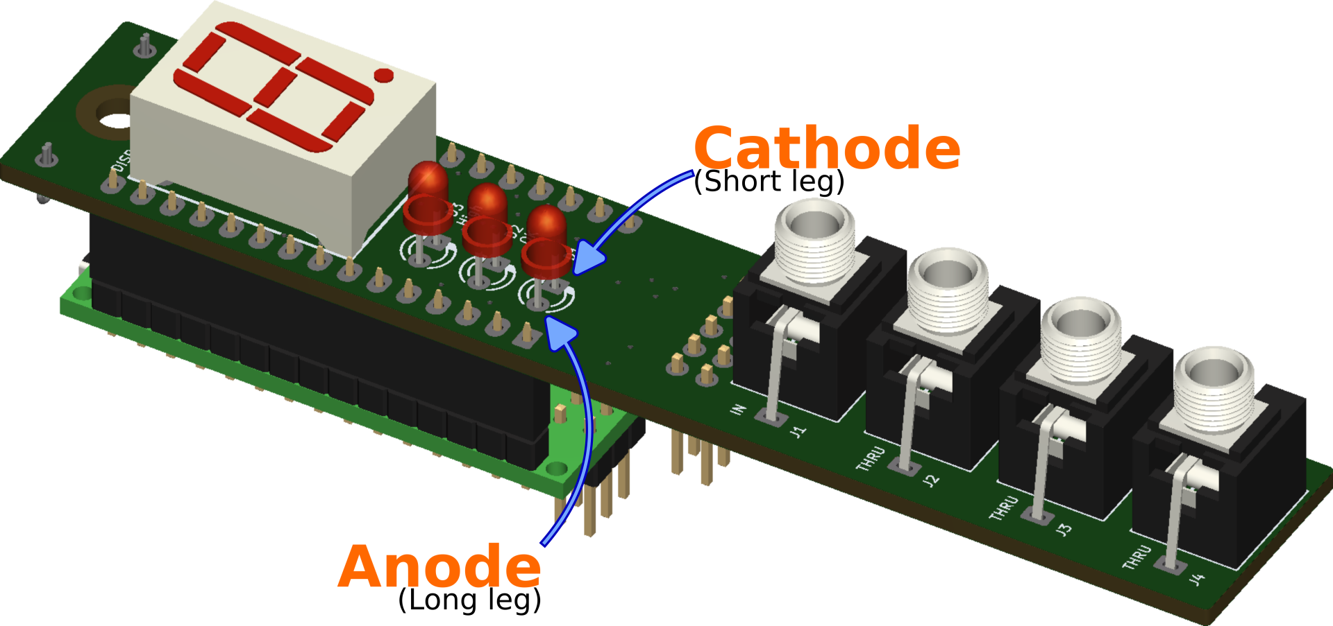
The 3 LEDs are polarized and need to be installed accordingly.
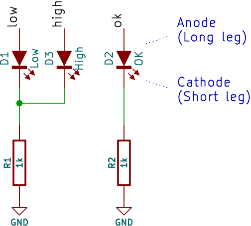
To determine the polarity of a Through Hole LED, there are several visual indications you can search for:
- The first is the flat side on the lower part of the transparent casing. Even though this flat side is much obvious on larger LEDs and can be difficult to spot on smaller LEDs, including 3mm ones, it indicates the Cathode (aka the “negative side”) and must be oriented toward the square shaped pad of the PCB.
The flat side is also represented on the silkscreen as a thicker line. - The second visual indication is the difference in length of the two legs. When the LED is new and the legs haven’t been trimmed yet, one is clearly longer than the other one.
The longest leg is the Anode (aka as the “positive side”).
The long leg must be inserted in the round shaped pad. - The third visual indication is a bit more difficult to spot and interpret, but is sometimes the only way to decipher the correct polarity of a LED, when both previous indications aren’t present.
You need to see through the transparent casing and watch the two internal metallic parts. One is much bigger than the other. The bigger one is the Cathode.
Please have a look at this article, on how to determine the polarity of an LED.
Display Setup
You must set S1 on the back of the PCB either to CA or CC, according to your 7-segment display.
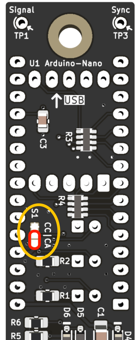
Use your soldering iron and add a tiny blob of solder on the correct position (short 2 pads together).
Be absolutely careful not to short circuit the 3 pads at the same time, as you would create a short circuit between +5V and GND.
I also created a small 3d-printed screen bezel to surround the 7-segment display. It adds a nice finish to the front panel.
Firmware
The firmware can be modified to change the complete behavior of the module, of simply change the way digits are displayed. It’s open source!
You can download it here: https://github.com/dhaillant/Tune-O-Matic
The code is based on the work by Jos Bouten.
Some modifications have been made to improve the accuracy and reliability of the measurements.
Previously, the frequency/note relation table contained errors. The data were either overlapping or incorrect for some notes. I created a simple ruby script to generate the correct frequencies, with an optional parameter allowing you to set the amount of cents for in-tune status and the possibility to tune A4 at a different frequency. The script is available here.
I also discovered that Amanda Ghassaei’s algorithm, as such, was too imprecise. For example, it was unable to find “440” when a 440Hz signal was applied on the input. Instead the software was displaying “442” or “437”. This is due to the speed at which the ADC samples the incoming signal.
As the atmega328 can’t reliably speeds up its ADC further (it’s already clocked at 500kHz), I first thought the global solution wasn’t viable, but I soon spotted that the data from the algorithm could be averaged. I chose the solution suggested in Make: AVR programming book (page 259): “Exponentially Weighted Moving Averages”.
The averaged values were much closer to the actual frequencies.
The final improvement was to increase the resolution by adding more decimals.
Other small improvements were made to the code (reshaped some digits, removed some unused code or reduced some memory usage).
Power Connection

-12V is marked by a white rectangle on the back of the PCB.
If your cable is correctly assembled and powered, then this side is where the “red stripe” goes.
Links
- Jos Bouten describes his own implementation of LMNC circuit at https://lookmumnocomputer.discourse.group/t/tune-o-matic-tuner/36.
- MyModularJourney made his own version and can be found at https://github.com/MyModularJourney/Tuna.
- The core of the firmware is based on Amanda Ghassaei’s algorithm https://www.instructables.com/Arduino-Frequency-Detection/
- Tuner on ModulaGrid
Documentation & downloads
- Download the Arduino firmware (https://github.com/dhaillant/Tune-O-Matic)
- Schematics (Tuner-1.0-schematic-2024-09-12.pdf)
- Interactive BOM (tuner-1.0-ibom-2024-09-17)
In the Tuner full kit, is the display common cathode or common anode?
Thanks
Indeed, the information was missing: the display in the kit is a Common Anode (CA) type. The firmware is already set for this type of display.