Tuner is a Eurorack and analog synth tuner utility.
This is an older version. Please, check the latest informations here.
This is the next prototype revision, introducing only small improvements.
Tuner is a very useful tool, which should be installed in all systems: It will help you keep your VCOs in-tune with other oscillators, or with other players in your band.
It’s based on the sub-circuit proposed by LMNC in his amazing Performance VCO.
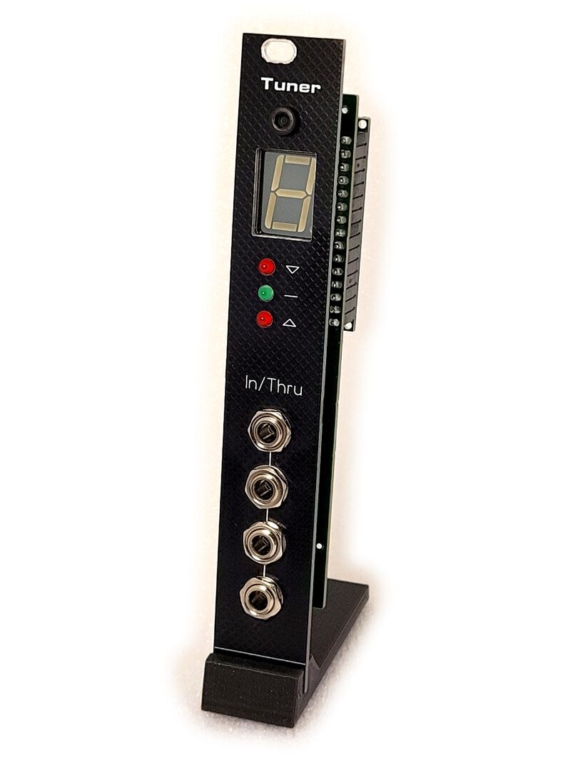
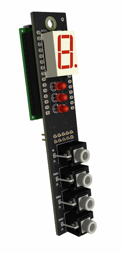
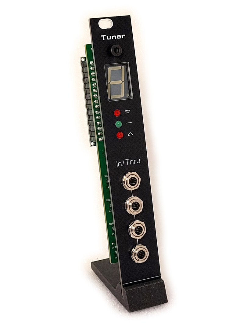
The module is equipped with 4 jack sockets, creating a passive multiple. You have the flexibility to input your oscillator’s signal into any of the 4 sockets, monitor the tuning, and subsequently route your signal to connect with other modules as needed.
Circuit description
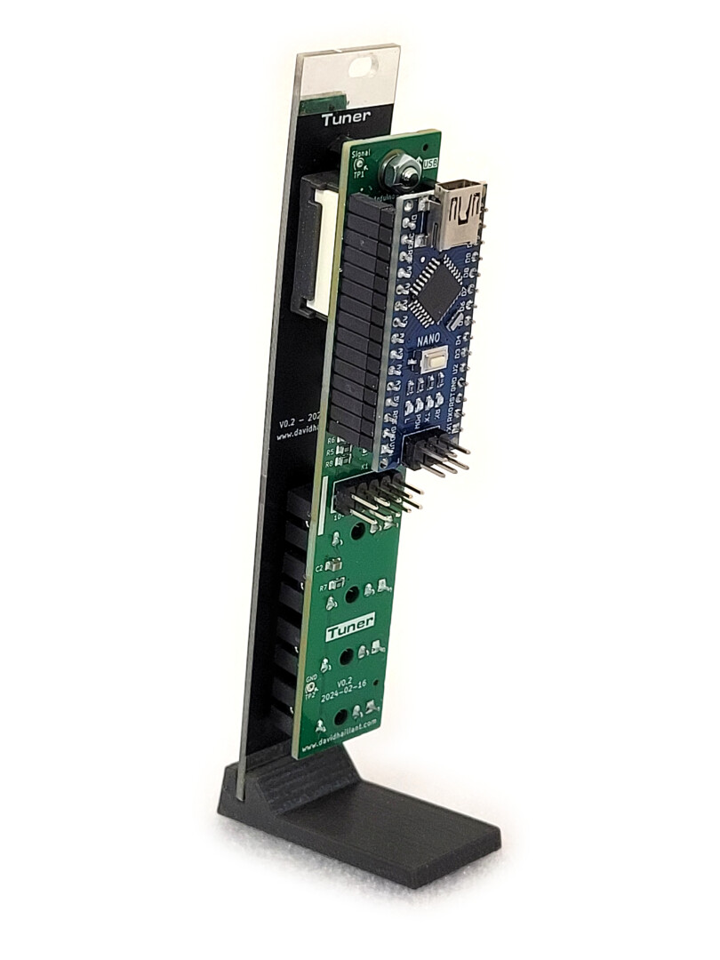
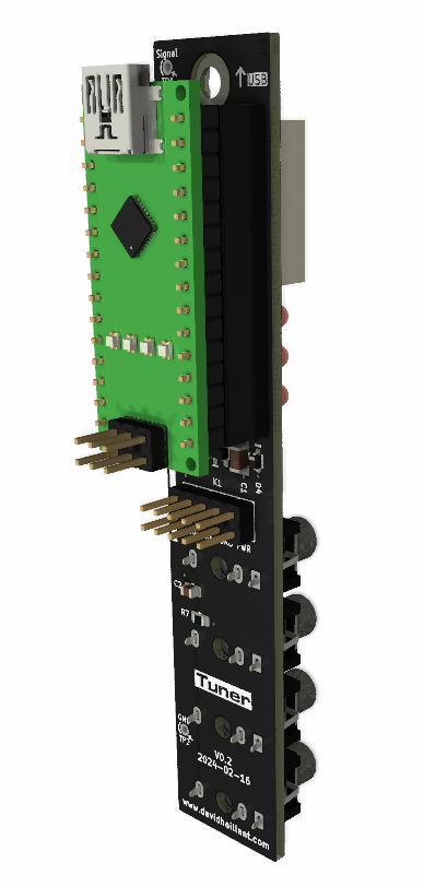
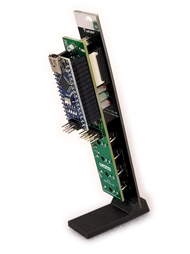
The circuit is relatively simple, featuring an Arduino Nano as the module’s core, along with input jacks, three indicator LEDs, and a single 7-segment display.
The Arduino Nano does all the hard work: it samples an analog signal, tries to detect the rising edges, measures the time between each cycle, averages the values, converts the result to a frequency, compares that frequency to a table of frequencies/notes pairs and finally displays the corresponding note. Additionally, it indicates whether the note is above, below, or in-tune.
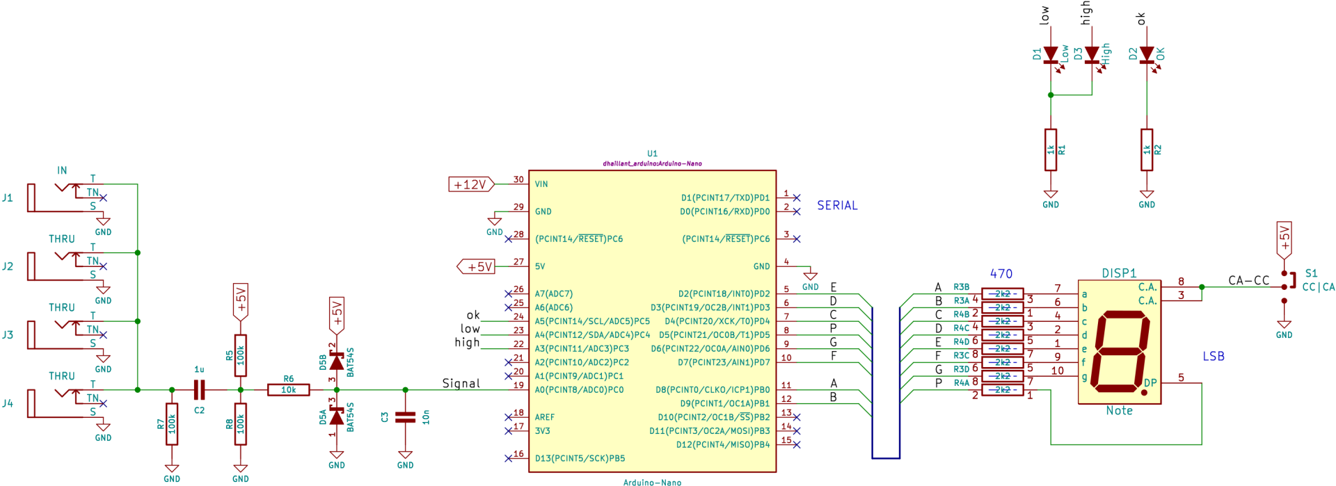
The Arduino ADC input is AC-coupled and DC biased at Vcc/2. Two clipping diodes protect the ADC circuitry from excessive voltages.
The 7 segment display can be either Common Cathode (CC) or Common Anode (CA) and the jumper S1 selects which type of display is installed.
The 4 jack sockets are passively connected. This way, you can insert your signal on any connector, and get 3 (passive) outputs. So, even if you don’t use the tuner feature, the module can still be used as a 1-to-3 passive multiple.

Firmware
The software is based the one written by Jos Bouten and has been modified to improve the accuracy and reliability of the measurements.
You can download it here: https://github.com/dhaillant/Tune-O-Matic
Previously, the frequency/note relation table contained lots of errors. The data were either overlapping or incorrect for some notes. I created a simple ruby script to generate the correct frequencies, with an optional parameter allowing you to set the amount of cents for in-tune status and the possibility to tune A4 at a different frequency. The script is available here.
I also discovered that Amanda Ghassaei’s algorithm, as such, was too imprecise. For example, it was unable to find “440” when a 440Hz signal was applied on the input. Instead the software was spitting out “442” or “437”. This is due to the speed at which the ADC samples the incoming signal.
As the atmega328 can’t reliably speeds up its ADC further (it’s already clocked at 500kHz), I first thought the global solution wasn’t viable, but I soon spotted that the data from the algorithm could be averaged. I chose the solution suggested in Make: AVR programming book (page 259): “Exponentially Weighted Moving Averages”.
The averaged values were much closer to the actual frequencies.
The final improvement was to increase the resolution by adding more decimals.
Other small improvements were made to the code (reshaped some digits, removed some unused code or reduced some memory usage).
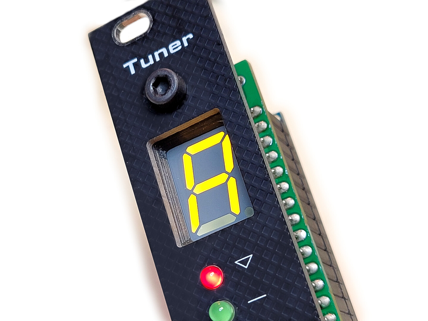
I also created a small 3d-printed screen bezel to surround the 7-segment display. It adds a nice finish to the front panel.
Links
- Jos Bouten describes his own implementation of LMNC circuit at https://lookmumnocomputer.discourse.group/t/tune-o-matic-tuner/36.
- MyModularJourney made his own version and can be found at https://github.com/MyModularJourney/Tuna.
- The core of the firmware is based on Amanda Ghassaei’s algorithm https://www.instructables.com/Arduino-Frequency-Detection/
- Tuner on ModulaGrid
Documentation & downloads
- Download the Arduino firmware (https://github.com/dhaillant/Tune-O-Matic)
- Schematics (tuner-0.2.pdf)
- Interactive BOM (tuner-main-0.2-ibom-2024-02-16)