
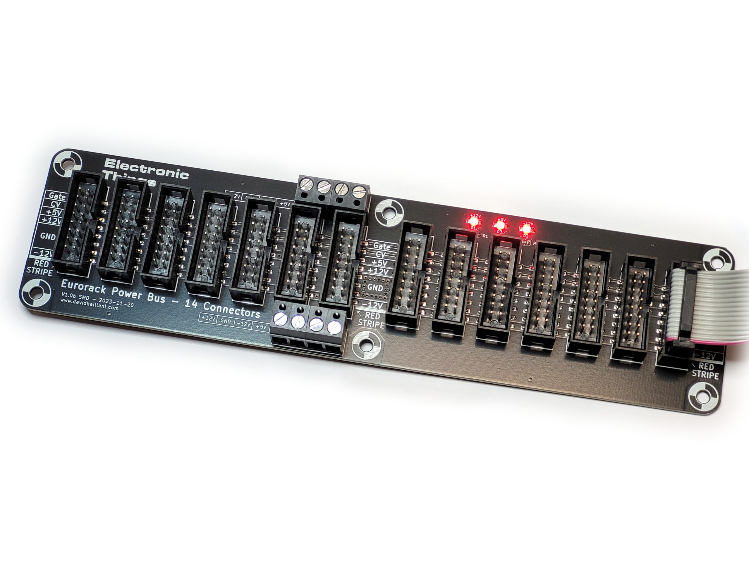
The Eurorack Power Bus with its 14 Euro connectors is back in an updated version.
There are different buses available, with various sizes and number of connectors.
The version 1.1 slightly simplifies the BOM and adds a second power input terminal, either for chaining to a second bus or to ease the installation as PSU cables can be wired either from the bottom or from the top of the case.
The Eurorack Power Bus board is a convenient way to distribute the required power voltages across a small-to-medium Eurorack system.
There are 14 Eurorack connectors so up to 14 modules can be powered at once. Two additional 16-pin DIL connectors are dedicated to Analogue Systems compatible modules. Plus, six 3-pin connectors are present for your powered 1U modules.
The bus can be equipped with a onboard +5V linear regulator.
The 3 LEDs let you know if the 3 power rail voltages are present. The form factor of the bus is 20cm long, 5cm wide. The short distance between the connectors ensures lower voltage drops under high current consumption.
BOM
Here’s a suggested Mouser BOM:
| 647-UVZ1H010MDD1TA | 2 |
| 604-WP710A10LYD | 3 |
| 621-1N4007 | 2 |
| 710-61201621621 | 14 |
| 534-8719 | 1 |
| 538-22-30-3364 | 1 |
| 575-199316 | 2 |
| 603-CFR-25JR-521K | 2 |
| 603-CFR-25JR-52470R | 1 |
| 511-L7805ABV | 1 |
(I’m not familiar with Mouser, so, I strongly encourage you to check twice the references provided above.)
The LEDs are plain, 3mm diameter, 1.9~2.0Vf and 2mA If.
The model I use is yellow/orange diffused.
The Screw Terminals are 5.08mm pin-pitch.
The resistors are either carbon film or metal film, 1/4W, axial leaded. Optional: Depending on the LED models, the value might be adjusted to get less brightness offset between the different voltage rails.
The optional +5V regulator is a generic 7805, 3-pin, 1.0A, 5V fixed voltage linear regulator in TO-220 package.
The capacitors for the 5V regulator are 2mm pin-pitch radial aluminum/electrolytic, 25V minimum.
The diodes for the 5V regulator are generic silicon rectifier diodes, 1N4004 to 1N4007 (1N4007 are usually cheaper and widely available).
Building the Eurorack Power Bus
The build process is simple:
Start by soldering the three resistors. The resistors are not polarized. R1 and R2 are 1k Ohms (Brown, Black, Red, Gold). R3 is 470 Ohms (Yellow, Violet, Brown, Gold).
See Resistor color code chart.
If you use the onboard +5V regulator, add now the two 1N4007 diodes. They are polarized. Follow the white band marking on both silkscreen and the diode case. The white band shows the Cathode side of the diodes.
Bend the leads of the +5V regulator U1 (7805) at 90°, according to the silkscreen.
You can either bolt the regulator to the PCB or solder the metallic tab to the square pad. Soldering the tab requires to apply enough heat to both the PCB and the regulator heat sink. The solder must flow under the metallic tab to effectively bond the regulator to the PCB.

If you intend to use Analogue Systems compatible modules, you can solder in place the two 16-pin DIL sockets. If not, you can simply skip this step.
The DIL socket is polarized: align the notch to the silkscreen marking.
If you intend to use the 1U connectors, you can nw solder the six 3-pin connectors. If not, you can simply skip this step. Those connectors may require some adjustment to be correctly aligned vertically. Try to solder one pin at a time and then adjust the position.


Interactive BOM (bus_eurorack-1.1-ibom-2019-01-17)
As usual, you can find the Eurorack Power Bus PCB on Tindie.
Just checking to be sure – If this board is supplied +12, -12 and +5 from the terminal screws, then the 7805, diodes, and capacitors are not required? (Notes do not mention capacitors, but they appear to be only needed if the 7805 is in use)
On a side note, is there a need for caps to stabilize the voltages on these boards? I know other distribution boards from other folks have them…
Hello Rob,
You’re right, if the +5V is supplied to the bus board from your PSU, there’s no need for the 7805 and the components surrounding it (the diodes and the capacitors).
Also, capacitors – except for stabilizing the 7805 – are useless on a bus board. Even if others use decoupling capacitors (and I did it too, in the past…) they are useless here.
A decoupling (or by passing cap) must be placed as close as possible to the source of noise (close to an IC for example) and at the input of the modules (for reservoir capacitors).