New revision for the Eurorack Compact Power Bus!
There are different buses available, with various sizes and number of connectors.
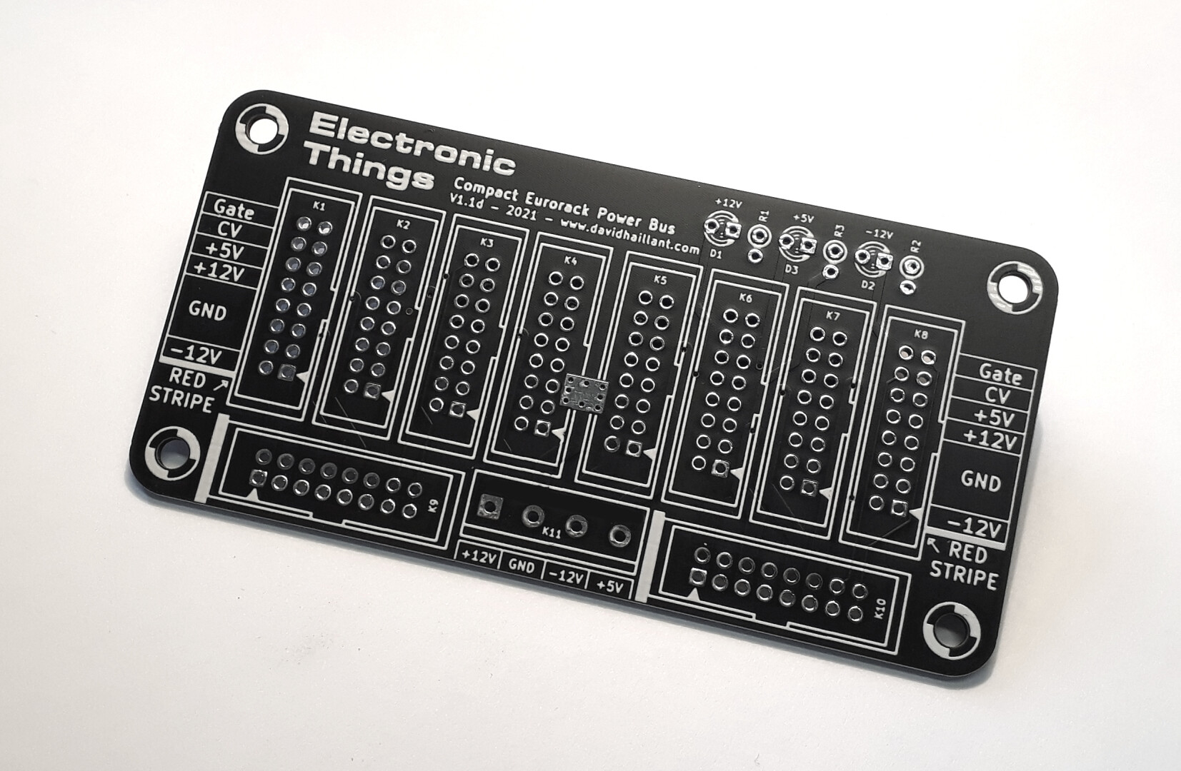
The Compact bus is one of the smallest yet powerful Euro bus in the world. Yes really 🙂 It’s only 10cm long but you can plug 10 modules!

About the components
Here are some tips on how to select the right components for your bus:
- The required voltage for the capacitors must be greater to the voltage they are connected to. As we use 12V in Eurorack, 25V is a safe minimum value. Any value greater than 25V is also fine. Often the 1µF are only available with 63 or 100V ratings.
Neither the temperature nor the life ratings are critical. 85°C is fine. - The resistors are of any type, carbon or metal, 1/4W (250mW) minimum, 1k or 1.5k ohms for the +12V and 330 ohms or 470 ohms for the +5V. 5 or 10% tolerance is fine.
- The LEDs are preferably low current versions but any LED is fine. Red, green or yellow are ok. Please avoid the blue ones as they require either more current or more voltage (you would need to adapt the resistors). 3 or 5mm diameter is fine.
- The 16-pin connectors are 2.54mm pin pitch, IDC pin arrays, boxed (shrouded) or not.
- The input connector is any 5.08mm pin pitch Screw Terminal. Or you can simply solder your wires directly to the board.
Construction details
The board is really easy to solder. There are, in this revision (1.1d), no more SMT device. Only Through Hole components.
Step by step assembly
I recommend to solder the smallest components first. This way you can put in place the components, flip the board on your desk and it will help you align the components vertically and make them sit correctly, at the same height, against the PCB.
- Start by soldering the 3 LEDs then the 3 resistors.
- Solder the 10 Eurorack connectors. I recommend boxed headers but some will prefer the unboxed ones. It’s your call! Eurorack Connectors are 2×8 pins, 2.54mm pitch.
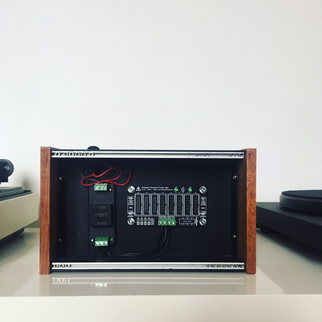
- Last step is the power input connector. You can use different solutions but the one I use and recommend is the Screw Terminal Block. It allows you to accommodate a lot of different power sources. The pin pitch is 5.08mm.
The LEDs are polarized. Check this article for correctly identifying LED polarity.
Power on
The board requires 4 power rails: +12, -12, +5 and 0V (0V is marked “GND” on the board). The +5V rail can be skipped if your modules don’t require it.
If you have some doubts about the difference between the -12V and the 0V, please read my previous post “Ground is Not your Negative Rail“.
When powered on, the LEDs should lit. If not, double check your solder joints and most important, check the polarities of both LEDs and your rails.