Connecting your module for the first time can be tricky. There are chances to destroy it.
Ok, what to do then? Well, you need to check the following points before pluging in anything, and most important : Never trust the red stripe.
- Is my PSU correctly delivering the +12 and -12 volts on the right rails? Use any simple multimeter to check the voltages.
- Is my PSU correctly connected to my bus (flying bus or bus board)? Again, use any cheap multimeter and test the rails. Some bus boards are equipped with LEDs (mine are). But if the LEDs are reversed mounted, then they’re definitely not to be 100% trusted. While you check the voltage rails, do not short +12 or -12 volts to ground!. Male pin header connectors are dangerous: the pins are quite exposed and your probe could easily slip between two pins and make a nasty short. Be careful!
- Is my bus (again, PCB or flying bus) correctly assembled? Watch for reversed shrouded connectors: Look for pin 1 (usually a little triangle). The key should be on the same side as pin #1.
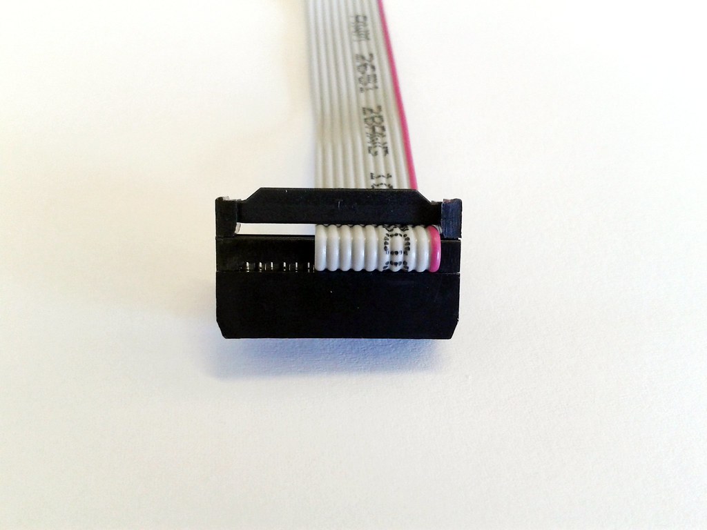
- Is my cable correctly assembled? Here’s one of the trickiest parts. The “red stripe” should be connected to pin one. But, sometimes not. The most important part here is to have pin 1 on each connector tied together: Pin 1 to pin 1, pin 2 to pin 2, and so on… I recommend to not use any suspicious cable. Ribbon cables are cheap so please, don’t keep an erroneous, misassembled cable, throw ’em! Really.
- Is my module clear enough on how to power it? There should be always, on every module, clear indications. I try to make my modules as clear as possible: connector pattern, pin #1 indication, red stripe position and, the most important, the positions of the voltage rails. But not everyone is cautious on this point and some just assume that red stripe is on the right lower corner of the module, or things like that…

The red stripe is sometimes blue, or grey, or purple or… sometimes there’s no colored stripe at all.
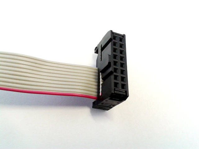
The ribbon can be connected from the left or from the right. This is not important at all. The retaining clip can be confusing at some point, as it’s reversing the cable direction, but only in appearance.