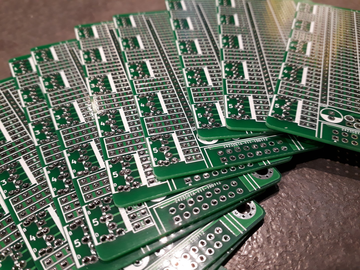
The Eurorack Stripboards are back in stock. You can find them at Tindie, at Thonk, at Synthcube and now at Elecrow.

![]()
![]()
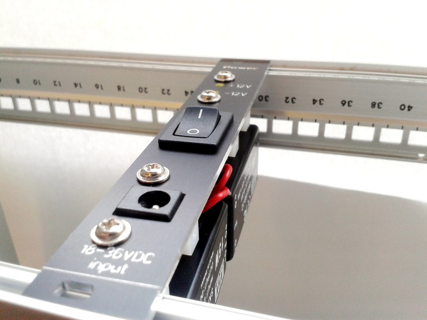
The Eurorack SMPS is the most powerful power supply I designed.
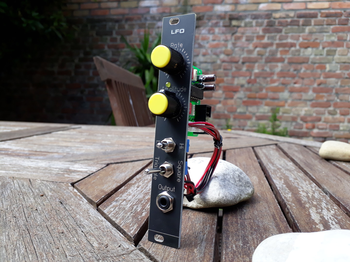
I released a new update of the Simple LFO, now in version 1.3.
The update is mostly about how the LED blinks.
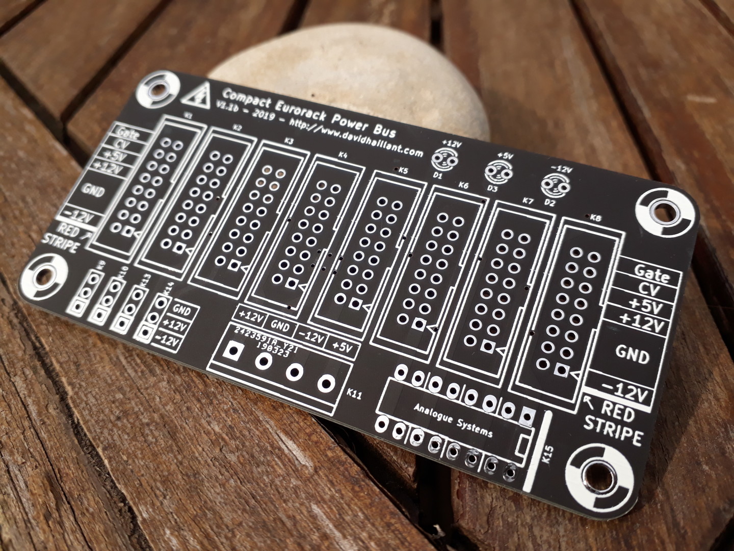
New revision for the Eurorack Compact Power Bus!
Continue reading Eurorack Compact Power Bus – version 1.1b B(L)ACK in stock
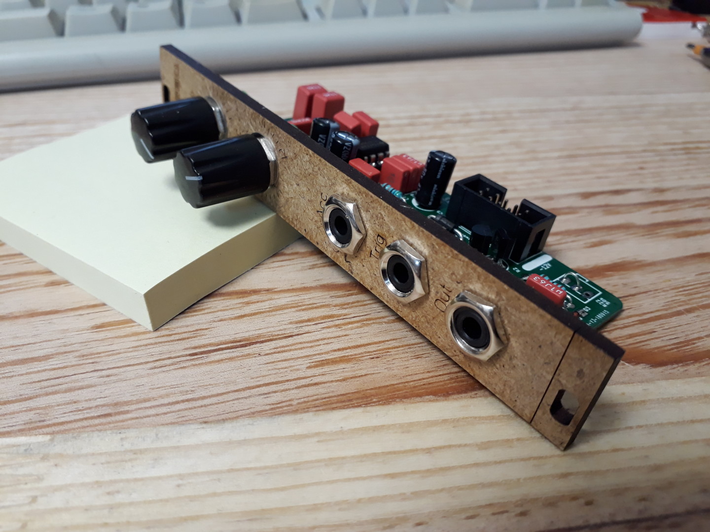
I made a simple clone of the Bass Drum section of the classic TR606 Drum Synth!
Continue reading 606BD – TR-606 Bass Drum clone
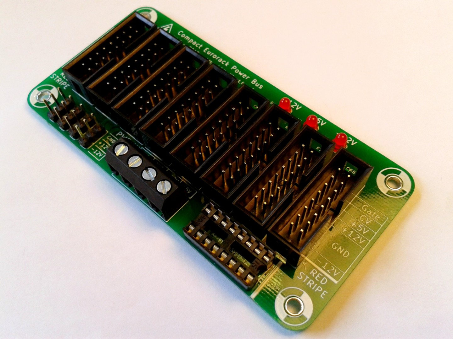
It is time for an update of the Compact Eurorack Power Bus! This is version 1.1!
An updated, corrected and simplified version of my Eurorack Stripboard is available!
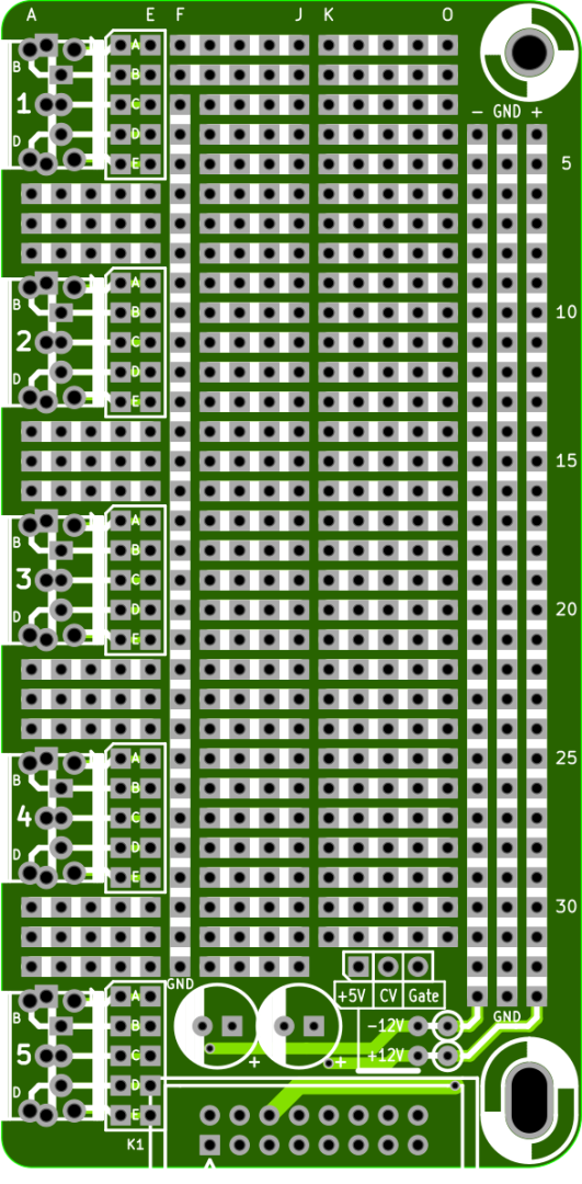
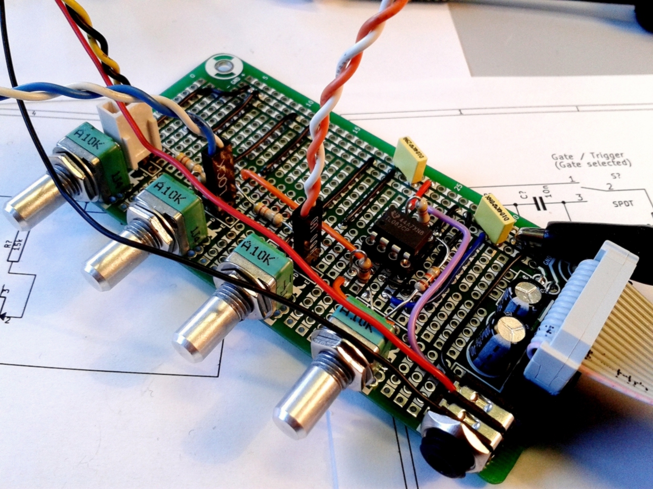
I always need to have, in my drawers, a quick and easy way to assemble and prototype small synth modules.
I think this the most convenient way to build a simple module. You just use it as a standard stripboard PCB but with neat additions.
Continue reading Eurorack Stripboard
New revision for the Simple LFO. It’s mostly a slight improvement of the output stage.
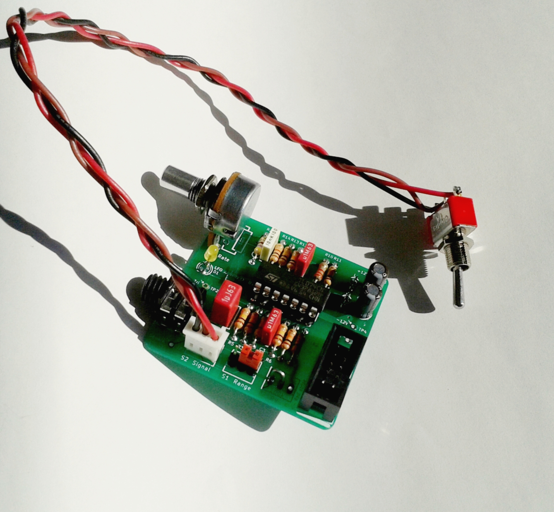
I added an buffering opamp on the output. Now, the output load doesn’t affect and modify anymore the signal frequency.
Continue reading Simple LFO update 1.1
After my first Compact Power Bus, I decided to go bigger and I designed a 14 connector Eurorack Power Bus.
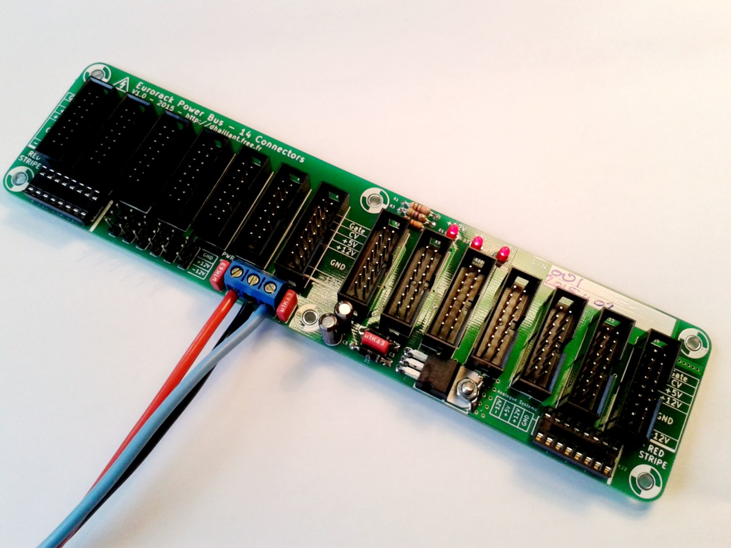
Continue reading Eurorack Power Bus – 14 Connectors