New revision for the Eurorack Compact Power Bus!
There are different buses available, with various sizes and number of connectors.
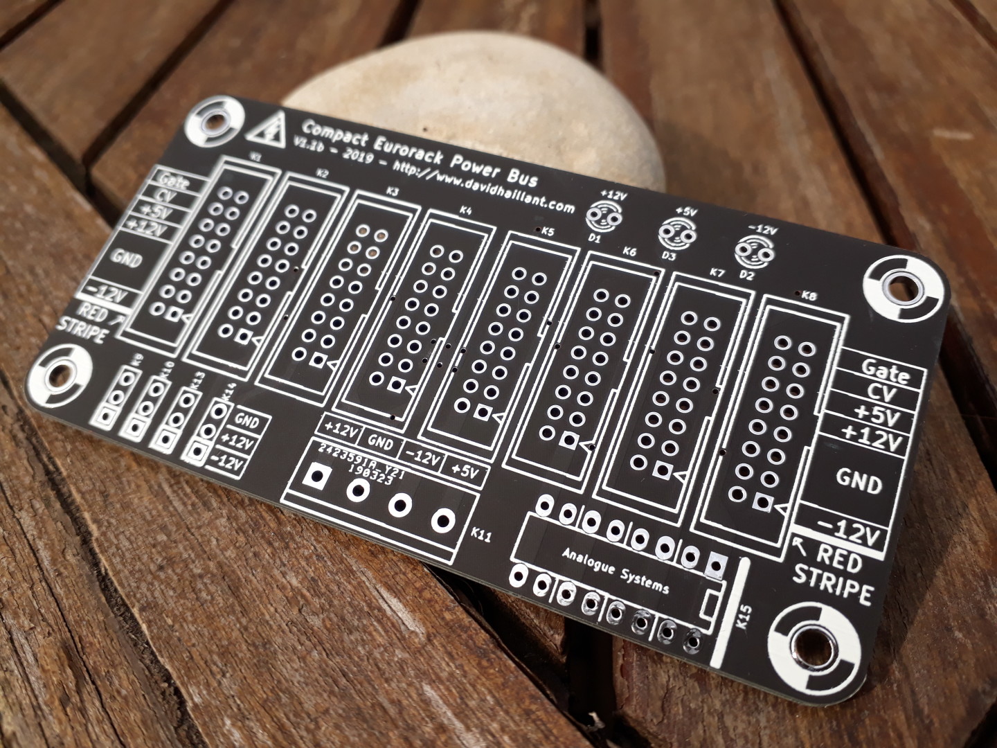
The Compact bus is one of the smallest yet powerful Euro bus in the world. Yes really 🙂 It’s only 10cm long but you can plug 8 modules plus 4 tiles and one Analogue Systems module!

About the components
Here are some tips on how to select the right components for your bus:
- The required voltage for the capacitors must be greater to the voltage they are connected to. As we use 12V in Eurorack, 25V is a safe minimum value. Any value greater than 25V is also fine. Often the 1µF are only available with 63 or 100V ratings.
Neither the temperature nor the life ratings are critical. 85°C is fine. - The resistors are 1206 SMD chips (thick or thin film), 1k or 1.5k ohms for the +12V and 330 ohms or 470 ohms for the +5V. 1, 5 or 10% tolerance is fine.
- The LEDs are preferably low current versions but any LED is fine. Red, green or yellow are ok. Please avoid the blue ones as they require either more current or more voltage (you would need to adapt the resistors). 3 or 5mm diameter is fine.
- The diodes are any reference in the 1N400x series. 1N4007 are often the cheapest.
- The regulator is any 7805 pin compatible regulator, in TO220 (or compatible) package.
- The 16-pin connectors are 2.54mm pin pitch, IDC pin arrays, boxed (shrouded) or not.
- The input connectors are any 5.08mm pin pitch Screw Terminals. Or you can simply solder your wires directly to the board.
Construction details
The board is really easy to solder. There are, on the bottom side of the board, 3 SMT resistors and 3 SMT capacitors. But don’t be afraid, those are 1206!
1206 SMT devices are big enough to be soldered with standard through-hole equipment. I personally use a cheap soldering iron.
What makes the difference is the thickness of your solder. I recommend 0.5mm solder wire. 0.3mm is better, but consider it only if you plan to do a lot of SMT soldering in the future.
Besides, it can be a great opportunity to experiment your first SMT soldering job. And don’t worry, if you aren’t successful, well, your board will still be fully functional! Only the LEDs might be inoperative.
Step by step assembly
Start by soldering the 6 SMT devices. Apply a small amount of solder on one pad of each component. with fine tweezers, place your component in its designated location, then reflow the solder with your iron while you slightly adjust the alignment of the component over the pads.
If you’re satisfied with the position, you just have to solder the second pad, and voilà!
If you do own an Analogue Systems module, you can solder the 16-pin DIP connector now. If you don’t have such module, skip this step.
Solder the 8 Eurorack connectors. I recommend boxed headers but some will prefer the unboxed ones. It’s your call! Eurorack Connectors are 2×8 pins, 2.54mm pitch.
Next, you can solder the four 3-pin “1U Tiles” connectors. Again, if you don’t use 1U Tiles, then simply skip this step.
I recommend to solder the LEDs now, before the big power input connector. If you flip your board, it will sit flat on your desk. It should be easier to align the LEDs vertically.
Last step is the power input connector. You can use different solutions but the one I use and recommend is the Screw Terminal Block. It allows you to accommodate a lot of different power sources. The pin pitch is 5.08mm.
Power on
The board requires 4 power rails: +12, -12, +5 and 0V (0V is marked “GND” on the board). The +5V rail can be skipped if your modules don’t require it.
If you have some doubts about the difference between the -12V and the 0V, please read my previous post “Ground is Not your Negative Rail“.
When powered on, the LEDs should lit. If not, double check your solders and most important, check the polarities of both LEDs and your rails.
Hi David,
Just to say how pleased I am with the Compact Eurorack Power Bus.
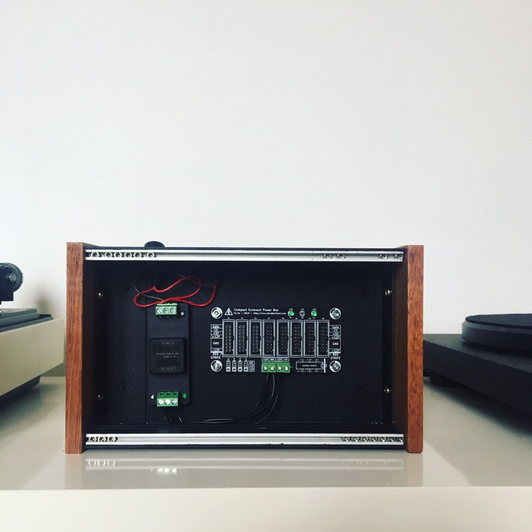
I have built my own take on the EMS VCS3 and will be using the CEPB to power an auxiliary cab (3U + 1U) to provide sequencing and reverb etc.
My main Synths are based around a 5U BOX66 (mainly .com modules) and 15U x 160HP of Eurorack modules. ( I will forward images when I receive your email by return).
I think I may purchase the larger Power Bus in the future, as I have just about enough room to build a 9U x 104HP cab to house a modular Vocoder and additional Percussion modules to support the top row of the 15U Eurorack which is slowly filling out as a dedicated Percussion Synth!
Very best wishes,
Mark