The UC (µC) Clock Divider is a clock/beat/step counter/divider, based on Arduino, with 8 outputs, configurable in code.
With a clock divider you can slow down a tempo, create rhythmic patterns or, with a audio signal at the input, get sub-octaves.
Dividing a Clock
Binary divisions
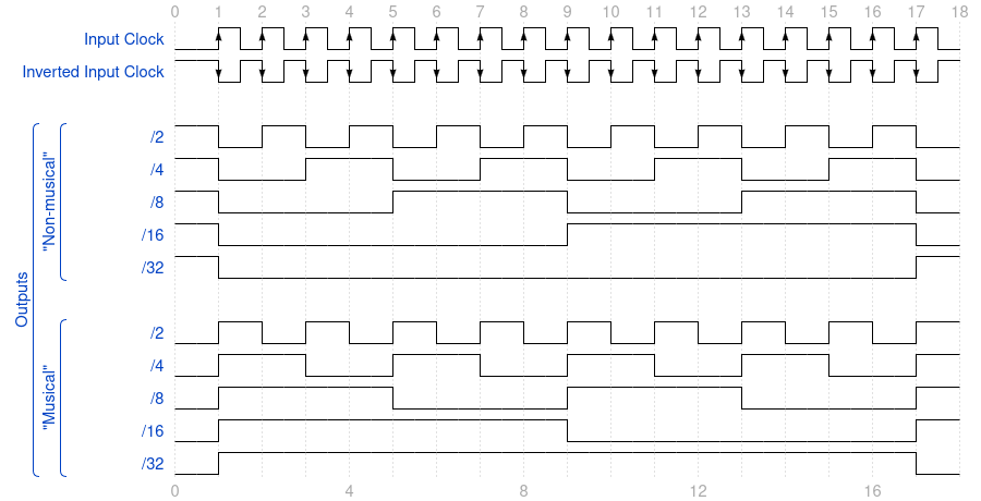
When we enter the subject of clock binary divisions, we rapidly encounter two different sorts: the “musical” and the “non-musical” binary divisions.
“Non-musical” term feels a bit rough isn’t it? This kind of binary division is in fact the accurate, natural and mathematical division of a binary number:
LSB  0101010101010101
     0011001100110011
     0000111100001111
MSB  0000000011111111
Hex: 0      ->      F
Or counting from 0 to 2^n. In the example above, with 4 bits, the Least Significant Bit (LSB) is the input Clock, and we count from 0 to F (15 in Hexadecimal notation).
And this exactly is the kind of division you get from the output of the various binary counter/divider chips, if you don’t modify both their input and output signals.
Unfortunately, if your goal is to trigger drum modules, this isn’t what you would generally need.
Usually, you want an instant “boom” on the first beat, not after some “tchak” or “dzzing”.
“Non musical” dividers can however offer exotic, off-beat patterns. that can be really interesting and worth exploring.
Now, to get this traditional “musical” pattern, you want something like this:
LSB  1010101010101010
     1100110011001100
     1111000011110000
MSB  1111111100000000
Hex: F      ->      0
Where, on the first clock pulse, every output is activated simultaneously. Nothing’s off-beat.
This is in fact counting from 2^n down to 0. In our example above, we count from F (15 in Hexadecimal notation) down to 0.
To transform the output of a dedicated binary counter/divider chip, you must invert both input and output signals.
These modifications make the otherwise very simple circuit a bit more complex, by adding inverting buffers (often transistors) on every single input and outputs.
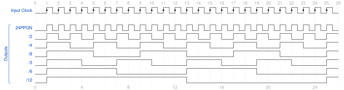
Here’s a diagram showing the two division timings graphically, side-by-side:
Ternary and other divisions
With UC Clock Divider, various non-binary divisions can be obtained. Ternary beats are a good example and can be derived, alongside binary divisions, in poly-rhythm patterns, by using 24, 48 or 96 PPQN Clock sources.
Polymeter rhythms are also possible. The difference between poly-rhythm and polymeter is the “independence” or “synchronicity” of the various outputs. And in fact, if you wait long enough, all outputs end synchronized at some point.
Here’s an example of a polymeter pattern:
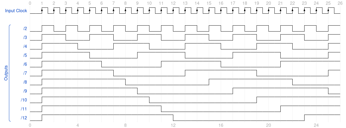
Ring counters are also possible:

The Hardware
The circuit is very simple and depends almost exclusively on the Arduino Nano module.
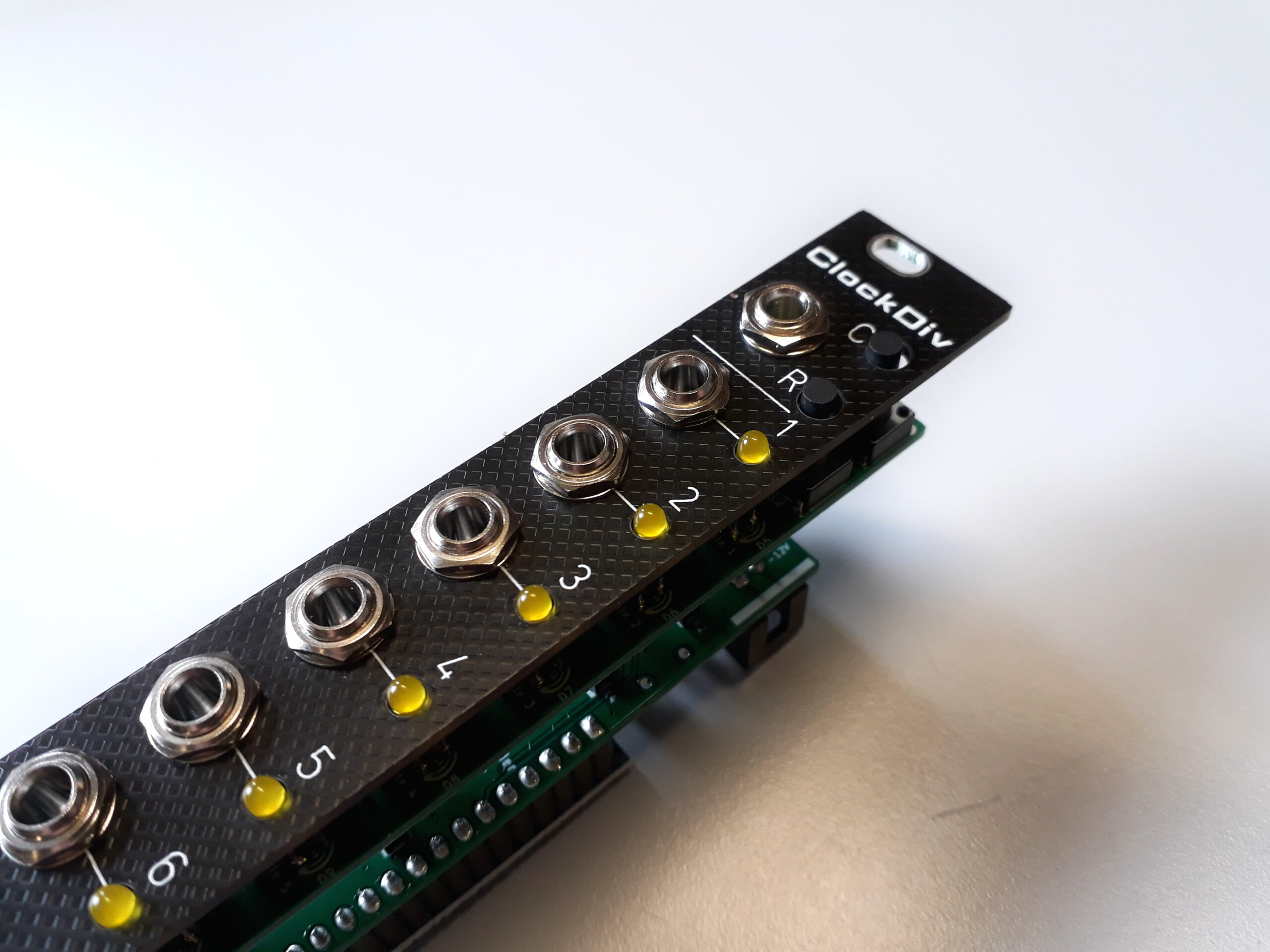
The input jack is stereo (TRS). Tip (T) is connected to Clock signal and Ring (R) is connected to Reset.
A +5V voltage triggers either Clock or Reset.
The outputs are +5V when ON and 0V when OFF. A 1k resistor protects against potential short circuits.
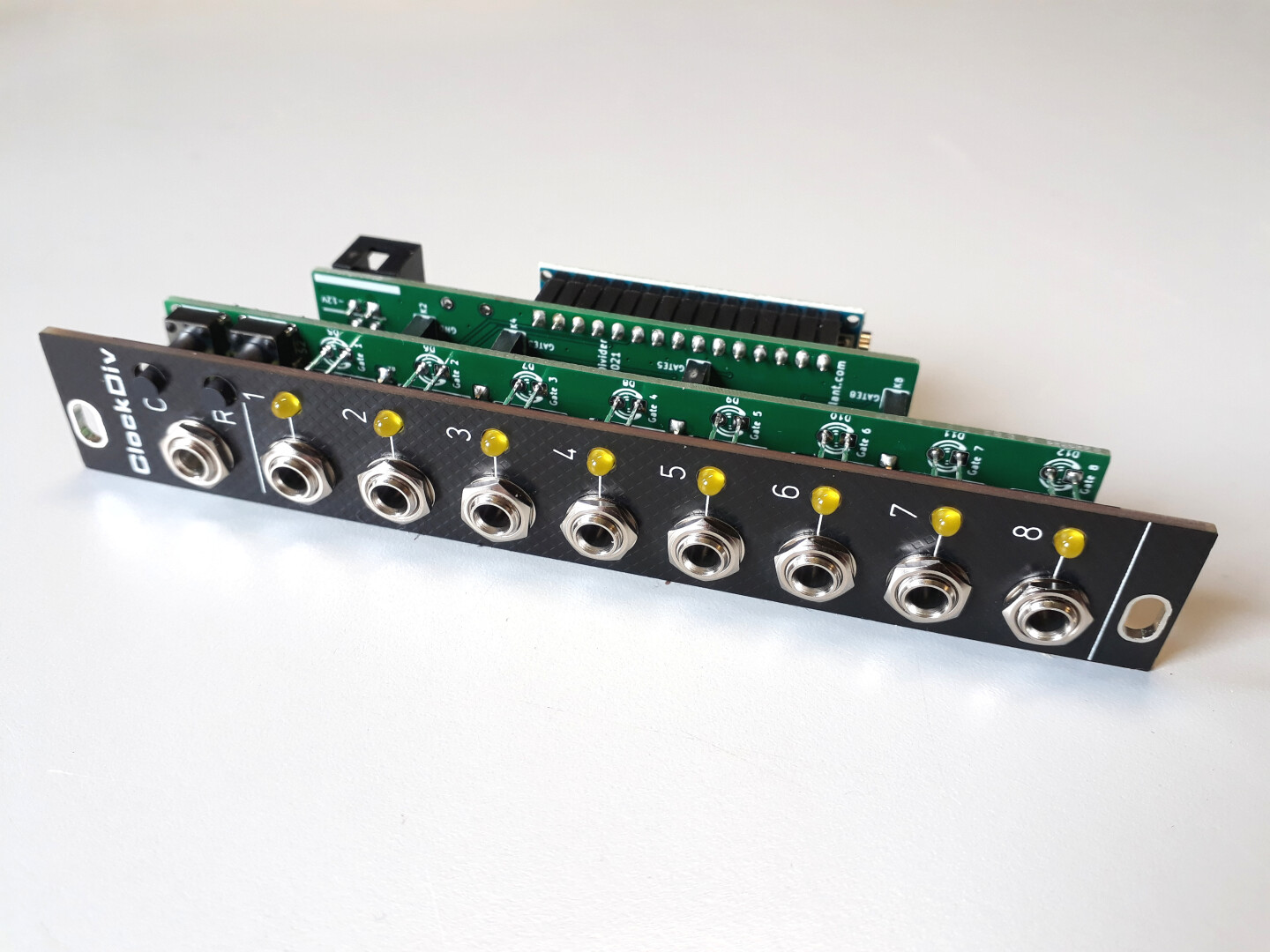
The module is distributed across two printed circuit boards. The first board contains the jack connectors. The second board houses the Arduino Nano and the Eurorack interface.
The components
There are both SMT and THT components.
The SMT components are all located on the bottom side of each board. They include the resistors, small capacitors and diodes.
The THT components are the jack connectors, the inter board pins/sockets, the Arduino Nano sockets, the power interface connector, diode and capacitor, the two tactile switches and the LEDs.
You can find a few recommended suppliers in the page Components and parts for all the specific or hard-to-find components.
About the jack connectors
The 8 output jacks are 3.5mm mono “Thonkiconn” (QingPu WQP-PJ301M-12, WQP-WQP518MA, WQP-PJ398SM…)
However the clock input jack is a green 3.5mm stereo Thonkiconn (PJ366ST).
About the tactile switches
You need to choose long tactile switches. They need to be around 13mm high. (The front panel is 10mm away from the front PCB, and the front panel is 1.6mm thick). I personally use TACT-613N-F by NINIGI.
The Code
Code examples can be downloaded from https://github.com/dhaillant/uc_divider
The Clock Divider code is based on hardware interrupts. One for Clock signal and one for Reset signal.
Each output has its own individual counter.
A positive voltage on Reset input triggers the reset function and sets all individual counters at 0.
A rising edge on Clock input allows the outputs with counter at 0 to be activated (ON)
A falling edge increments each counters by 1. If counters have overflowed (based on settings in code) they are set back to 0.
The main loop activates the outputs based on their respective counters and the presence of a voltage on Clock input.
Downloads
- Demo Code (https://github.com/dhaillant/uc_divider)
- Schematics (uc_divider-1.0-20220131.pdf)
- Interactive BOM – Front PCB (uc_divider-front-1.0-ibom-2021-12-07)
- Interactive BOM – Rear PCB (uc_divider-back-1.0-ibom-2021-12-07)
- Assembly drawings (uc_divider-1.0-Assembly-20220510.pdf)
 You can find the UC Clock Divider on Tindie!
Hi David,
I want to build this on stripboard. The schematic refers to several SMD components. Do you have advice on through hole components for BC847 and BAT54S? Thanks in advance.
Kind regards,
Thomas
Hello Thomas,
BC847 can be replaced by any NPN transistor. For example BC547.
BAT54S is just two (Schottky) diodes in series, in a single package. So you can use any diodes, two 1N4148 in series should probably work.
Hope it helps.
David
Hi!
Thanks for a great build! I’ve had lots of use for it. I think I might have found a tiny bug in your code:
In MyButtons.on(), it appears that lastDebounceTime is updated for any/both button presses, instead assigning the last debounce time for each button individually, or am I reading the code wrong?
If not, it could easily be fixed by using a lastDebounceTime[_num] array.
Just a heads up!
Best regards
Erik
Hey Erik!
Thank you for your suggestion! I contacted Luther who wrote that code, and he said that you were correct and it would make the code fancier.
Anyway, please, feel free to modify and share the code if you think it could help anyone else.
Also, I’d love to see your module in your setup 🙂
Have fun!
Thanks for your reply! I wound up rewriting everything, for my own amusement and preferences.
There actually are no huge differences – if any – from a user perspective. However, the code is written to use interrupts, and is tested on an Nano every which I came across for cheaper – compared to a regular nano – when I sourced the components. This means that the code is not tested on a regular nano board.
If anyone is interested I’ve made the project public at: https://github.com/ErikErikErikErikErik/Clock-divider
I’d be happy to take pointers (no programming pun intended) in case I’ve missed something.
If you have other code ideas for your module, I might have some spare time. Just hit me up!
Best regards
Erik
Hi Erik,
thanks for your efforts!
In particular it was interesting for me to copy the input with a by-1 division as a thru port to save on multiples, so I upgraded my module to a Nano Every. However it does not work as intended, because the pulse on that output is rather short than mimicking the input pulse duration. Anything we can do about that…?
Best, Hanso