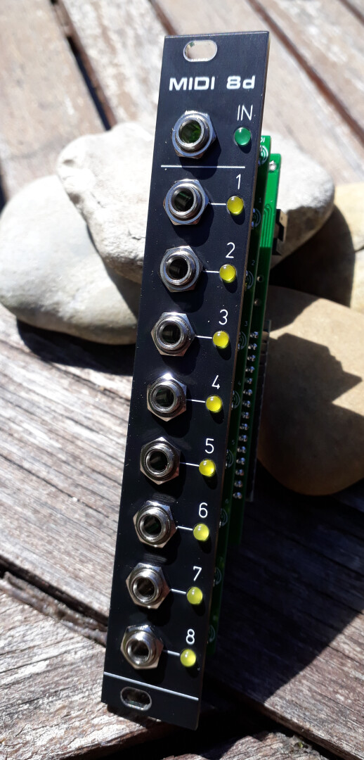
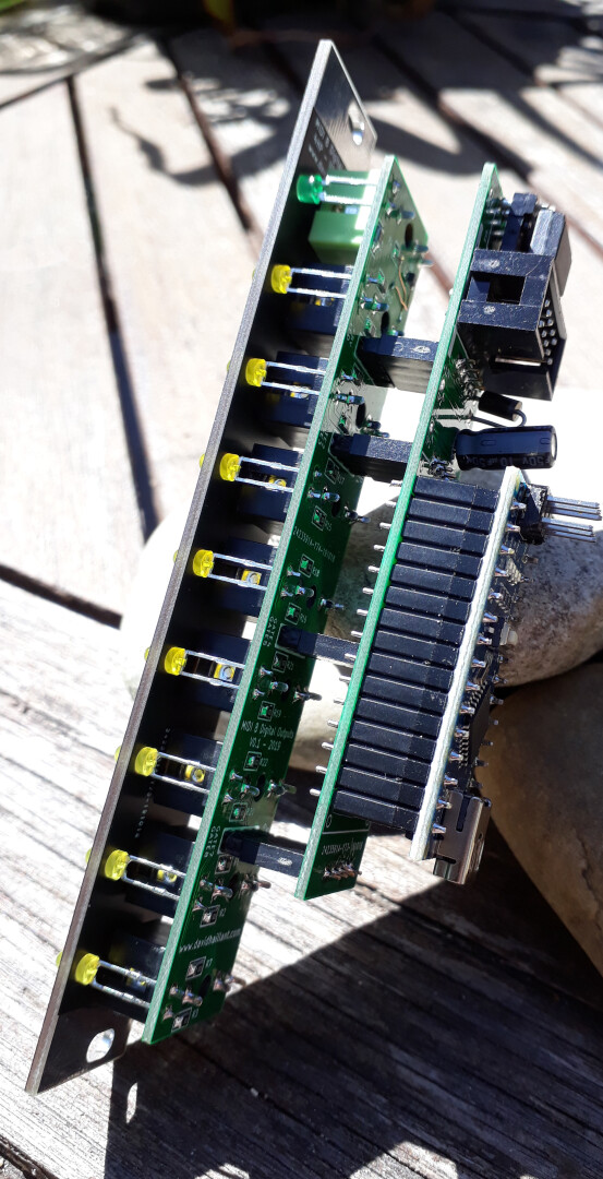
MIDI8d is a simple yet powerful 8 Digital Outputs from a MIDI/TRS input connection.
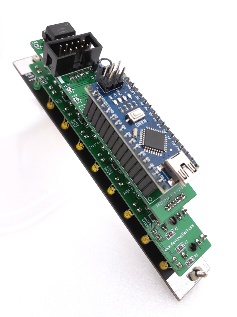
The core of the MIDI8d is the classic Arduino Nano.
Different firmware (Arduino sketches) can be uploaded, to adapt or completely change the behavior.
Typical uses are:
- 8 Drums outputs, reacting to MIDI Channel 10 (notes 36 to 43)
- MIDI Clock ticks, with various time divisions and Start/Stop Gate outputs
MIDI input
The MIDI input jack is a Stereo (TRS type A) connector.
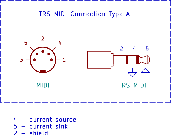
The Tip corresponds to the Sink signal, the Ring is connected to the Source.
The MIDI input circuit is pretty simple and the main component is the high speed Optocoupler 6N137 (U1). The output is pulled-up by R5 and is active low.
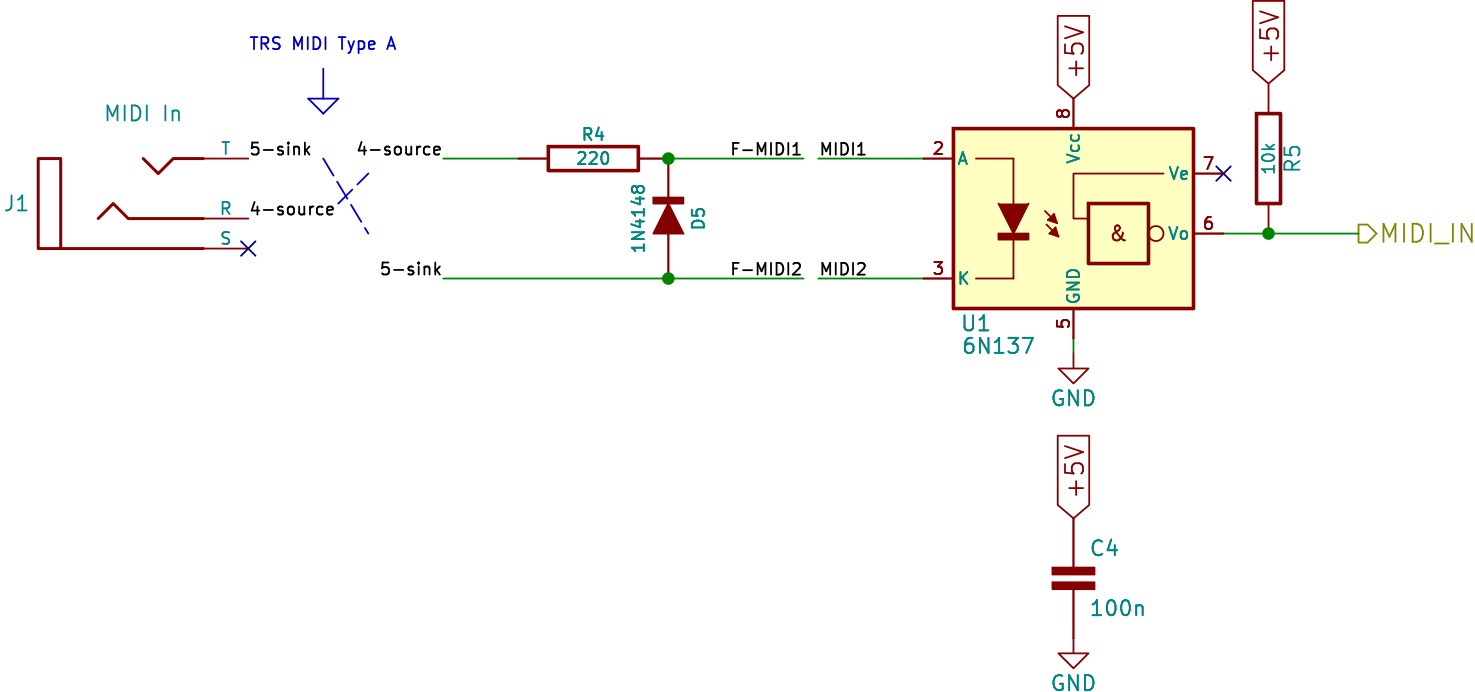
Firmware
Open source firmware can be found here: https://github.com/dhaillant/midi8d/
Several examples are provided (8 gates from MIDI channel 10, MIDI channel activity monitor, MIDI clock breakout, etc).
BOM
For a detailed BOM, please have a look at the Interactive BOM web page below in “Downloads & documentation” section.
If you choose a PCB set with pre-assembled SMD stuff, you have some Through Hole components to solder yourself:
| Quantity | Description | Link |
|---|---|---|
| 9 | 3mm LEDs (yellow, 2mA, typ. KingBright L-934LYD) | |
| 8 | mono jack sockets | Thonk |
| 1 | stereo jack socket | Thonk |
| 4 | 4-pin female sockets (2.54mm pin pitch) | |
| 4 | 4-pin male pin arrays (2.54mm pin pitch) | |
| 1 | 6N137 DIP optocoupler | |
| 1 | 8 pin DIP/DIL socket | |
| 1 | 5 x 2 pin array for Eurorack power connector | |
| 1 | 1N4007 or 1N5819 diode | |
| 1 | 10µF electrolytic capacitor (25V minimum) | Mouser |
| 1 | Arduino Nano | |
| 2 | 15-pin female sockets (2.54mm pin pitch) |
Downloads & documentation
- Interactive BOM (midi2drum-1.0-ibom-2021-05-17)
- Schematics (midi2drum-1.0-20210517.pdf)
- Source Code on Github
- Wiki on Github
Hi David,
Just been looking at the MIDI Clock code with the view to buying the PCB / Panel soon.
Quickly tried compiling the code from the github site and it failed, error on Line 73:
pinMode(MIDI_LED, OUTPUT);
Think this definition should be:
pinMode(MIDI_LED_PIN, OUTPUT);
Compiled ok with that change.
Will be it touch soon,
Cheers,
Bob
p.s. the MiniSynth built a while back is working fine
Hello Bob,
Thank you very much for pointing this out!
Indeed I made a typo here. The Github version is now updated with the correct pin definition.
Thanks
Hi David,
Thanks for the unexpected ‘extra’. Built both modules and all working fine.
Need to re-arrange the rack and expand it to give them a permanent home.
Cheers,
Bob
Hello. Thanks for uploading these ideas. I ask you the following: I have several Atmega328 chips that I want to use. They are not arduinos. My idea is to compile the INO file and convert it to HEX to load into them. Is there a midi or other library I should consider for compiling? Thanks again.
Hi, this seems amazing but I am looking to make the opposite way, gates > MIDI out, and I am a complete modular newbie. Do you believe I can use the SAME hardware and just change the arduino code to get it listen to triggers and output MIDI?
Thanks a lot!
Hi Felipe,
Unfortunately, the MIDI interface in the MIDI8d can’t be reversed (It would require some hardware modifications).
Maybe you could have a look at https://www.divergentwaves.co.uk/module/drumfiend/ which is a “trigger-to-MIDI processor”.
I could try to design one myself, someday, it could be useful for sure! One more project! ^^
Thanks a LOT, I’ll check it out! Looking forward to your version, as this one seems like a really accessible build for beginners like me!