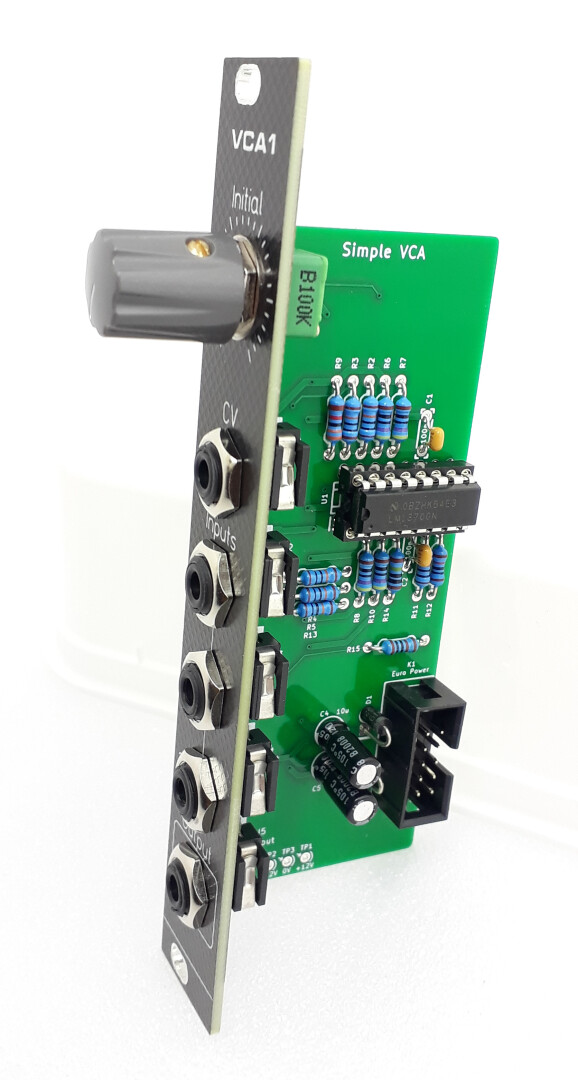
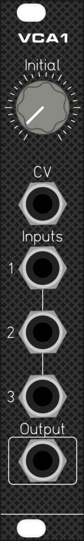
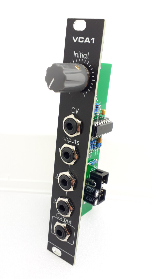
The Simple VCA is a single-chip Voltage Controlled Amplifier module in Eurorack format.

It’s a great first DIY VCA project: you can build it in a very short time using just a handful of common, off‑the‑shelf components.
This VCA can function as a variable volume control, a variable amplifier, a mixer, and more.
It features three audio/signal inputs that are mixed together.
Circuit description
The Simple VCA uses only one LM13700 (U1). This chip contains a dual Operational Transconductance Amplifier (OTA) – two OTAs in a single package – along with two independent Darlington transistor buffers.
Unlike a classic op‑amp, an OTA can modify its gain via a dedicated control current input pin.
Additionally, an OTA’s output is a current, whereas a standard op‑amp outputs a voltage.
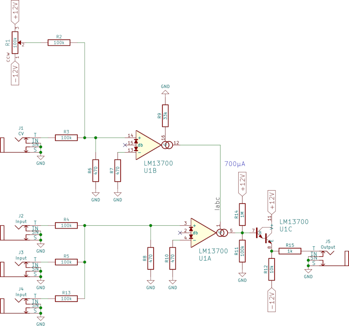
The circuit is very straightforward: the three input signals are mixed together via resistors R4, R5, and R13. The resulting signal is then significantly attenuated by a voltage divider (R8), as the LM13700 can only accept small voltage swings.
The signal enters U1A at pin 3 and exits as a current at pin 5, with its gain set by the amount of Iabc current injected into pin 1.
This current is then converted to a voltage and offset via R11 and R14 before being boosted by the Darlington transistor buffer stage (U1C).
Finally, R15 protects the output against short circuits.
Since the OTA’s pin 1 requires a control current (Iabc) and a spare OTA is available, U1B is configured as a voltage‑to‑current converter.
The CV signal is a mix of the voltage from jack J1 and an “Initial” setting from potentiometer R1. This mix is created by resistors R2 and R3, then heavily attenuated by voltage divider R6.
Resistor R9 sets a fixed gain factor for the CV. U1B outputs the resulting Iabc current at pin 12 and feeds it directly to pin 1.
Of course, the circuit needs power. Here is the Eurorack power input connection:
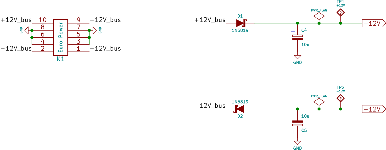
And here is how the LM13700 itself is powered:
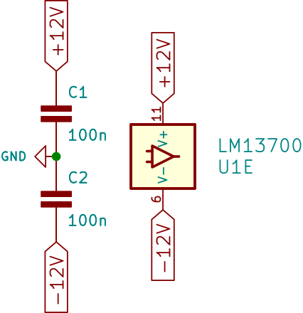
Two decoupling capacitors, C1 and C2, are placed close to the two power supply pins.
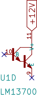
Darlington buffer U1D (pins 9 and 10) is unused in this circuit.
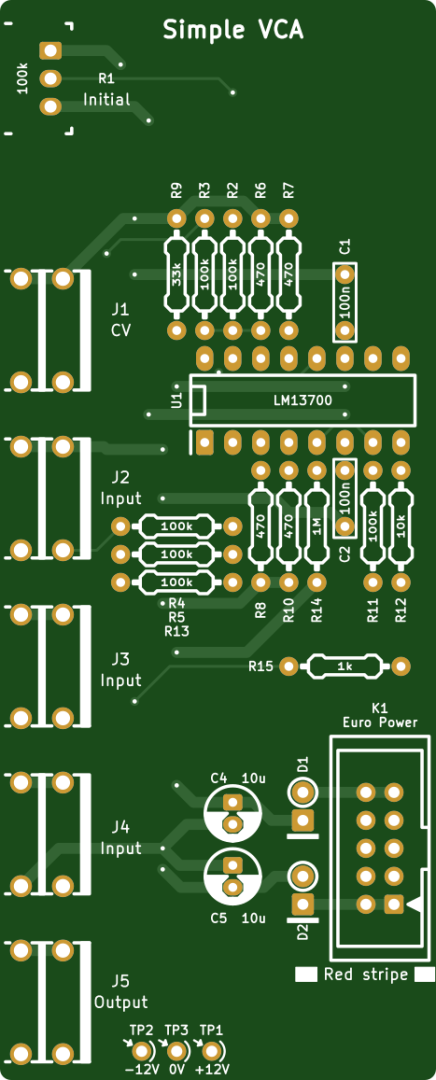
Components
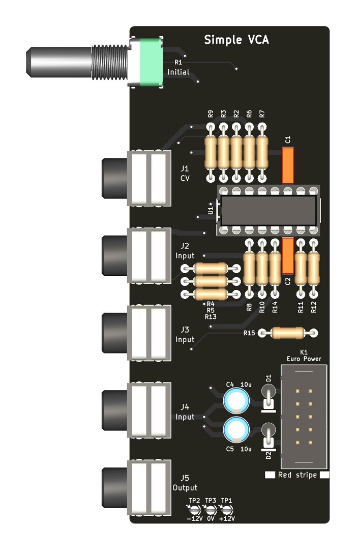
Jack connectors
The Jack connectors are Cliff CL1384.
Assembly guide
Follow the step-by-step assembly guide for Simple VCA.
Nice touch having the voltage test points on the PCB!
Potential builders should be aware the DIP version of the LM13700 went out of production a year or so ago. As of late 2022 you can still get it but not as readily as before — DigiKey and Mouser no longer have it, Tayda and Thonk do. The SMD version is still produced, so when DIP supplies dry up entirely, a converter board like the Chip-Quik PA0005 or PA0005C might be usable to put the surface mount chip in a through hole footprint, depending on how much clearance there is around the footprint.
Thank you Richard for pointing this out!
However, there seems to be some clones available: Friends reported that they were working.
Xinluda XD13700 at LCSC for example.
Eventually, if the DIP package turns into pure unobtainium, I’ll do a SMD PCB version.
Thanks so much for putting this up! I just built one from the schematics on a protoboard; it was a nicely straightforward build using parts I had on hand. The pot on mine is a slider, since that was the mountable 100k I had available quickly, so it ended up a 6HP unit. I need to make a final faceplate — the current test version is printable transparency film — but it otherwise works great. Thanks again!
I’d love to see the final result 🙂
I have some images up at https://taperwolf.tumblr.com/post/694911099597996032/ and https://taperwolf.tumblr.com/post/695046777004572672/ . I still need to drill out the faceplate (my old cordless drill isn’t quite up to the challenge), so it’s not quite done, but you get the idea.
And https://taperwolf.tumblr.com/post/695258561991901184/ has the finished module. (The initial labeling didn’t work out.)
Thanks for sharing this! I’ve built the barebones of it on a protoboard (like Taper Wickel) and I’m seriously impressed that a VCA could be made with such a low part count. I deliberately laid out the protoboard so that there’s space for a second one next to it – big brain move!
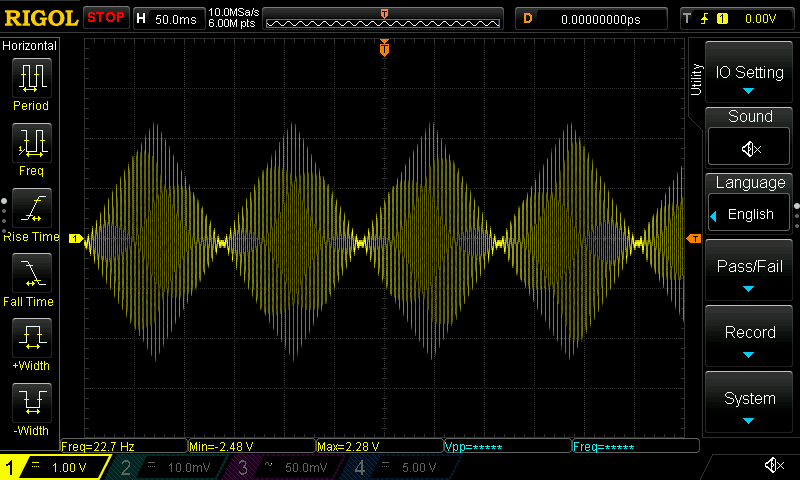
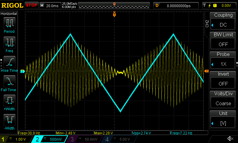
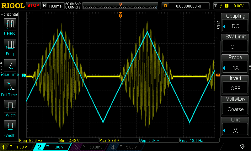
I’ve just popped a demo of it hooked up to an oscilloscope here, in case anyone’s interested 🙂 https://www.instagram.com/p/ClUJJBog1dN/
Are the audio inputs to lm13700 expected to be AC coupled, that is without DC. would there be harm in putting .1uf caps between each jack tip and 100k for j2, j3 and j4?
Got to your website thru Kristian Blasol’s video’s (Modular in a Week) Great Modules David. I have built the LFO and the VCO also and all work great. As an intermediate hobbyist these are great. People like you bring it down to my level so that I can also have some fun with these. Thanks for all that you do.
Hello Peter,
Thank you very much for your kind words!
If you have any questions, please let me know.
Cheers