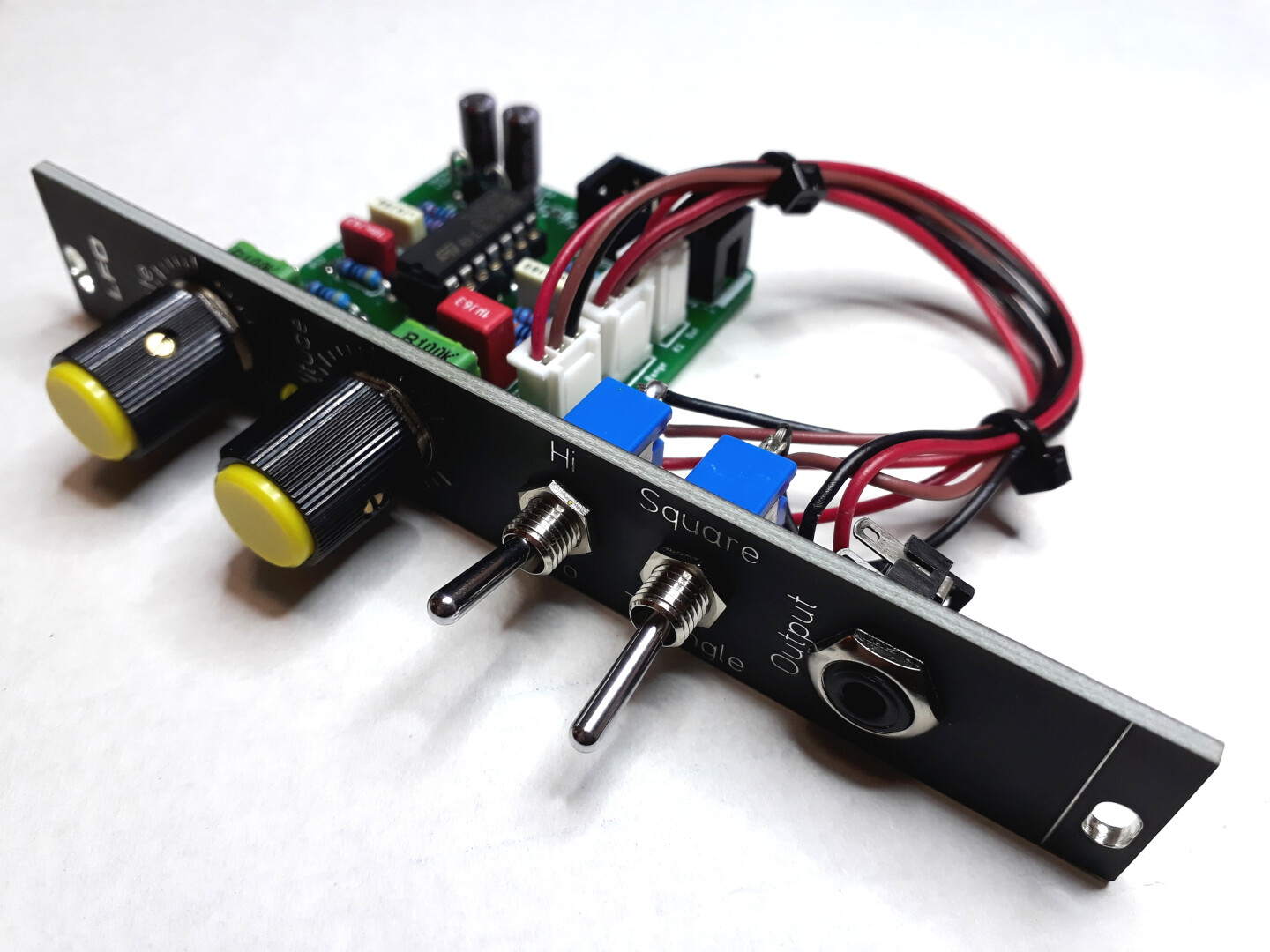
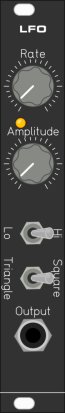
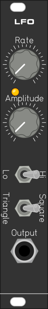
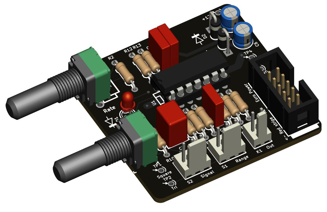
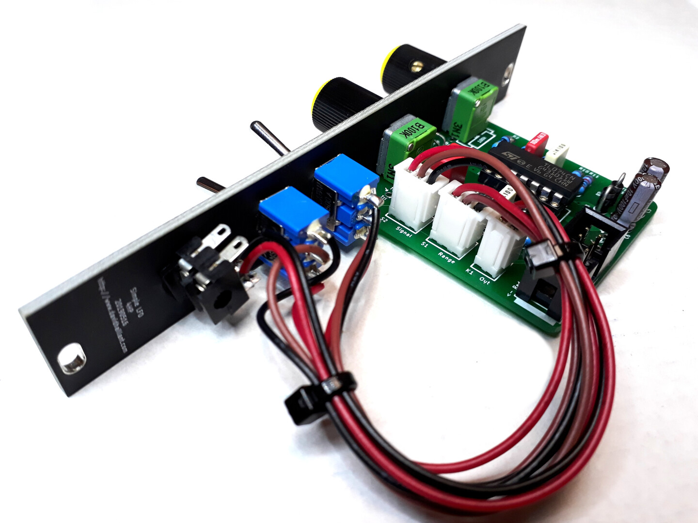
The Simple LFO is a… simple LFO module for your Eurorack system.
Two waveforms available: Triangle and Square wave. Adjustable amplitude and Low/High range switch.
It’s easy to build, easy to understand and maintain. Only easy-to-find through-hole components.
Description
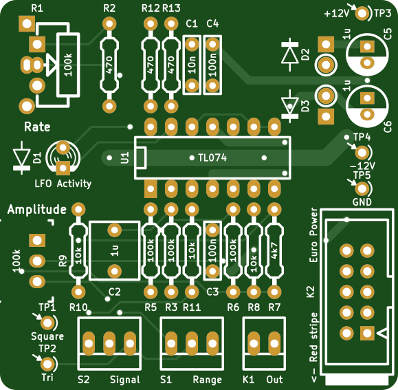
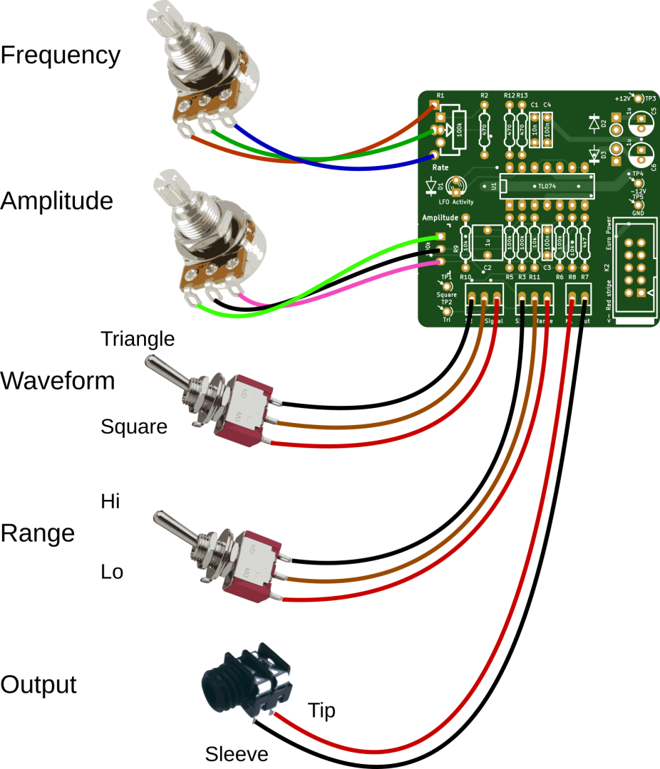
The Simple LFO module is a Low Frequency Square and Triangle Oscillator, designed to be integrated into an analog synthesizer. It is compatible with the Eurorack format: 10-pin power supply connector and voltages (+12V, 0V and -12V). The frequency, ranging from 2.5 mHz up to 250 Hz (audio domain), is adjusted with the potentiometer R1 (Rate). There is no Voltage Control (CV) input.
Powered at -12 / +12V, the maximum output amplitude swings between -6.3 / +6.3V peak-to- peak for the triangle waveform and -5V / +5V for the square waveform. The output signal
can be attenuated with the potentiometer R9 (Amplitude).
The waveform is selected between Triangle and Square with the switch S2 (Signal). If required, both waveforms can be used, separately, but in this case, only one waveform can be attenuated via R9. Also, there’s a phase shift of 90° between the two signals: the square wave is “low” when the triangle waveform is “going up”, and the square wave is “high” when the triangle wave is “going down”.
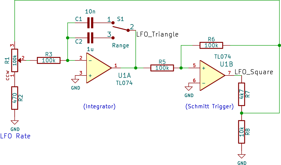
The oscillator is based around two operational amplifiers. The first op amp (U1A, R1-R3, C1, C2) is an integrator circuit. The second part (U1B, R5-R8) is a Schmitt trigger comparator.
The output is buffered, insuring a stable frequency, independent of the output load. It can be directly linked to the CV input of any voltage controlled analog module. U1C is the output buffer. U1D drives the LED.
This circuit has been inspired, among others, by:
Revisions
V1.5:
- Simplification: R4 removed
- Output Normalization: Square waveform reduced by half
V1.4:
- Corrected an inversion in the LED circuitry, which prevented the LED to be lit as expected.
Simple LFO is available on Tindie!
Frequency Ranges
| Range | Lowest Frequency | Highest Frequency |
|---|---|---|
| LO | 2.5 mHz (0.0025 Hz) | 2.4 Hz |
| HI | 250 mHz (0.25 Hz) | 245 Hz |
Power requirements
| +12V | 10mA |
| -12V | 10mA |
About the BOM
Many component values are not critical in the Simple LFO. It’s a robust circuit which can tolerate many experiments and modifications of the values.
The 2 input capacitors C5 and C6 can have any value between 1µF and 100µF. A common value is 10µF. One important thing is the minimal operating voltage of C5 and C6: it mustn’t go below 25V.
TL084 or TL074?
The TL08x and TL07x are interchangeable. They are pin-to-pin compatible, the voltage levels are identical.
The TL07x family is a lower noise version of the TL08x family.
However, the signal levels involved in synth modules is probably somehow immune to noise problems.
So feel free to use whichever version you want.
Potentiometers
- https://synthcube.com/cart/synth-diy/parts/potentiometers/alpha-9mm-round-shaft-pc-mount-pots
- https://www.thonk.co.uk/shop/alpha-9mm-pots-right-angle/
- http://smallbear-electronics.mybigcommerce.com/alpha-single-gang-9mm-pc-mount/
- https://www.musikding.de/Alpha-Pots-9mm
Assembly procedure
This is a step-by-step assembly procedure.
Click on the links below to view in full page:
Last minute details
About LED D1
The LED D1 is a dual LED (bi-colored). It is lit in one color for positive excursion of the selected waveform and lit in other color when the signal goes negative.
To address either one LED or the other, the polarity has to be reversed. For example, if pin #1 is positive and pin #2 is negative, the first LED is lit. If you reverse the voltage (pin #1 negative and pin #2 positive), the second LED is lit.
You can use a regular LED instead, and place it in any polarity you want, but it will be lit on only one excursion (either positive or negative) of the selected waveform.
About the diodes D2 and D3

D2 and D3 are Protection Diodes: they protect against reversed voltages on the power connector. You can override the diodes with shortcuts (jumper wires or clipped legs from components).
They are to be mounted vertically, over the circle printed on the PCB, with their Cathode pin pointing Up. The Cathode side of the diode is the one with the white ring.
In other words, the Cathode must be connected to the square pad while the Anode is connected to the round pad.
The 1N4007 can be replaced by any 1N4000 diode (1N4004 etc) or by equivalent Schottky diodes 1N5817, 1N5819 etc. Schottky diodes have lower forward voltage.
Wiring
Videos
Documentation
- Schematics (lfo-1.5b-20210205.pdf)
- Interactive BOM (lfo-1.5b-ibom-2020-10-01)
- LFO 1.5b BOM & doc (LFO-1.5b-BOM-doc-20210228.pdf)
External links
- Reddit / SynthDIY Forum – “NOOB Question about the David Haillant LFO”
- exsertus.com – Modular Synthesizer Project Part 6 – LFO
- lookmumnocomputer.discourse.group – Adding sync to an LFO
- Circuit Lab – Haillant LFO with sync
- SYNTHÉTISEUR MODULAIRE DIY – SIMPLE LFO
The Simple LFO has been inspired, among others, by:
- The ASM-1 Synthesizer by Gene Stopp and Magnus Danielson
- Music From Outer Space Sound Lab Mini-Synth by Ray Wilson

Capacitor R2 ceramic 1uF is nowhere to be found at the moment, is there any other alternative? electrolitic use would be easy to solve
C2 can also be a plastic-film capacitor. You can find such reference at Reichelt for example (https://www.reichelt.com/de/en/film-capacitor-1-0-f-50v-rm5-mks2-50-1-0–p172681.html) or at Mouser (reference: 505-MKS2-1/63/10A)
Dios te bendiga deibid <3 muchas gracias 😀 for answering back quickly
Hello! I am currently breadboarding your lfo but the minimun frequency i get is about far from your mentioned 25mHz (would be about 400 seconds period time), i get about 7.5. i am using 1uf capacitor. Any idea what might be wrong?
Thanks for your schematics!!!
Assembled one of the units I ordered … works great!
I used an on-off-on switch for the High-Low range, and put a 1uF cap across pins 1 & 2 of the chip. When the switch was in the OFF position, only the 1uF cap was connected, producing waveforms up to 2KHz. In Hi or LOW position, the 1uF cap was in parallel with the normal caps, reducing their frequency by about 10%.
HI,
is there a way to make an amplitude of triangle waveform to be +- 9V?
what is needed to start? can i just put voltage to input and some speaker on output ?
Hey, well, since the LFO is self-oscillating, so yes, it will start working as soon as you power it up, and you can get the signal at the output.
However, the output is at Eurorack levels, which can sometimes be too hot for certain devices. Just be cautious with it.