The Eurorack SMPS is the most powerful power supply I designed.
It’s also a very simple and safe solution: Linear power supplies usually need a transformer, which implies to deal with Mains voltages (the exception is the Mini Dual Power Supply which just requires a Wall Wart).
The Eurorack SMPS instead is powered by a regular laptop-style power supply.

Build instructions
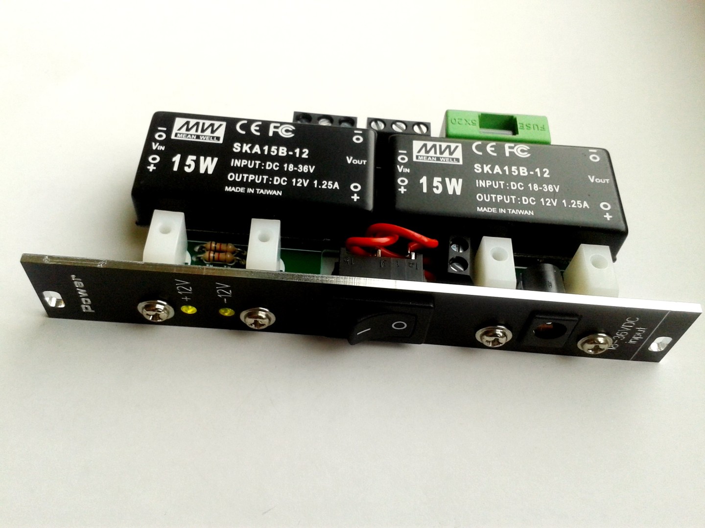
The build process is pretty straight forward. The two DC-DC converters hosts the complex circuitry.
I recommend to start by soldering the two converters.
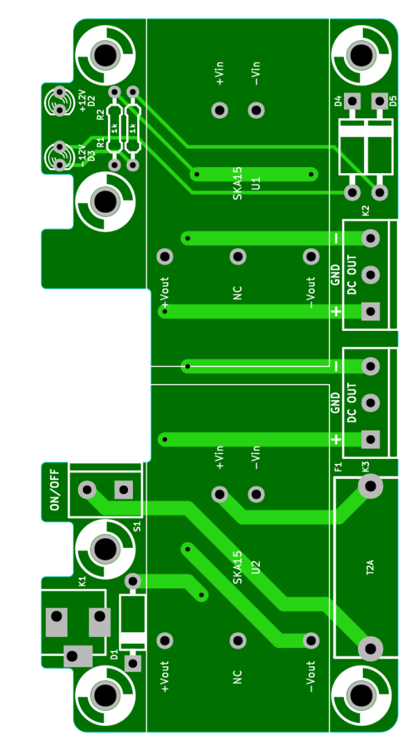
Then solder the two resistors and the three diodes. Attention, the diodes are polarized. Align the white band on the diode to the white marking on the PCB.
Attention, D1 is not a regular Silicon Diode. It’s a TVS (Transient-Voltage-Suppression) diode (P6KE 39A). See Datasheet.
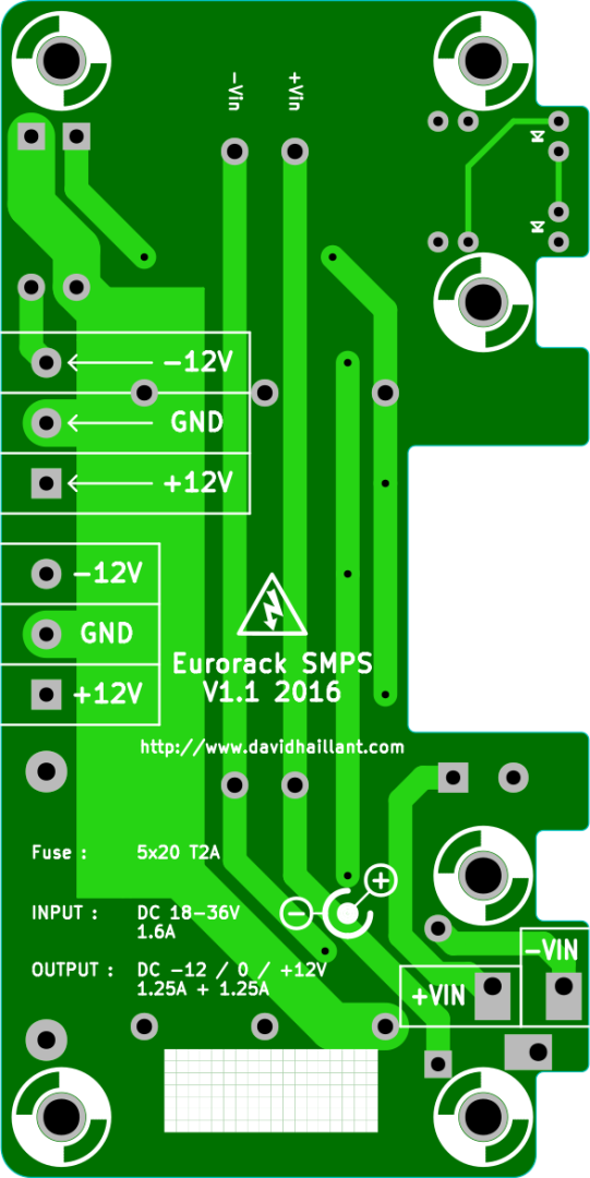
Then solder the 2 output terminal connectors, the fuse socket and the DC input jack socket.
If you want you can also use a screw terminal for S1. If so, you can solder it now.
Bolt the 4 standoffs to the PCB.
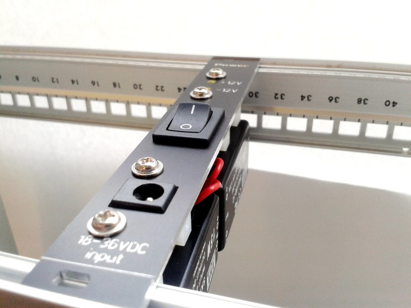
The two LEDs are also polarized. The longer leg is the positive side. With the front panel, I recommend to measure the distance required for the LED to be correctly placed through the panel, then bend the legs accordingly.
The distance from the PCB is important too. The center of the LEDs is at the same elevation as the center of the brackets’ hole.
A bit longer than necessary is better than too short.
One of the last steps is to bolt the front panel in place, then cut two short length of wire, tin the tips, and solder them to the switch. Then, connect the wires to the screw terminal S1, through the switch’s cutout in the front panel.
Snap in place the switch.
Place the fuse (T2A) in its socket (or in the cover of the socket).
Tests
Before plugin in anything, triple check your build, and specifically the polarities of the diodes.
Do not connect your PSU to the bus of your system! Check first if everything is safe!
Plug in the DC input jack socket K1 the barrel jack connector from a PSU Brick (24V is one of the most common value) and toggle the switch. The LEDs should lit immediately.
With a multimeter, check for presence of the voltages on K2 and K3: The black (negative) probe of your multimeter is in contact with the center position (“GND”) and with the red (positive) probe, measure the voltages at the two other pins on K2 and K3. You must read -12V and +12V.
Hi David! Beautiful, beautiful design!
I just have one question — do you have a BOM anywhere for this device?
I ordered one of your board/panel sets from Tindie for this PSU and I’m struggling to find the part values for some of the smaller components.
I can’t wait for the boards to arrive so I can start assembling this though. It looks absolutely brilliant. Thanks for sharing your work!
Hey! Thank you very much 🙂
You’re right, I completely forgot to add some BOM information. So, I just uploaded the interactive BOM and I’ll add later more information.
If you can’t find a specific component, let me know.
Best wishes
David
Thank you so much David! I just got the boards (your PSU and the SLMS) in the mail yesterday and I have to say the designs are *gorgeous*. I can’t wait to put them together. Thanks for the prompt reply, the nice note on the package, and the BOM upload! I’ll let you know how it all works once I’ve got it in my little test skiff. ^^
All the best from sunny Seattle!
-J.