It is time for an update of the Compact Eurorack Power Bus! This is version 1.1!
So what’s new?
I removed the CV and Gate buses “matrix” system. In version 1.0, each CV and Gate signal was separated and if you wanted to link them, there was a 2×8 pin header to manually interconnect them.
Now, all CV and all Gate signal are already interconnected.
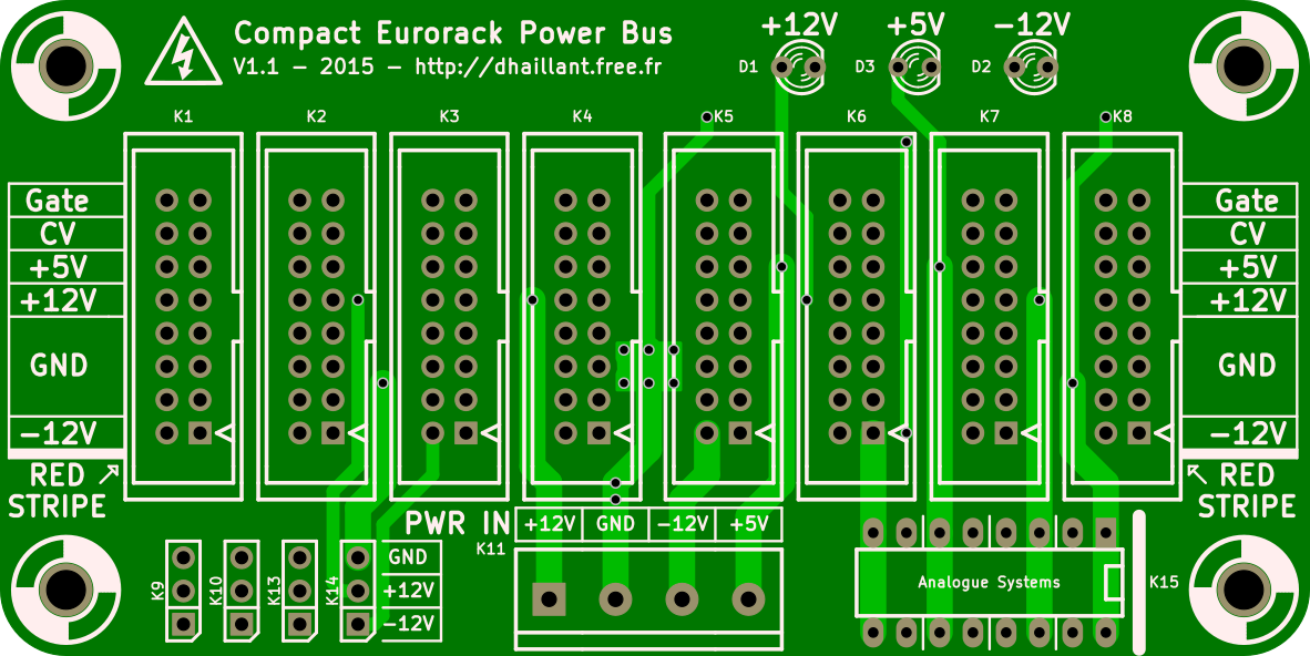
I added 4 connectors for the “1U” tile modules. I recommend to solder them only if you need them, as voltage rails are exposed.
I also added one Analogue Systems DIL-16 power connector. No need then to use an adapter.
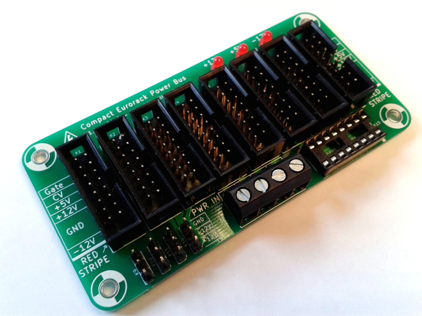
The power input connector is now one simple 4-pin screw terminal block instead of the previous two blocks.
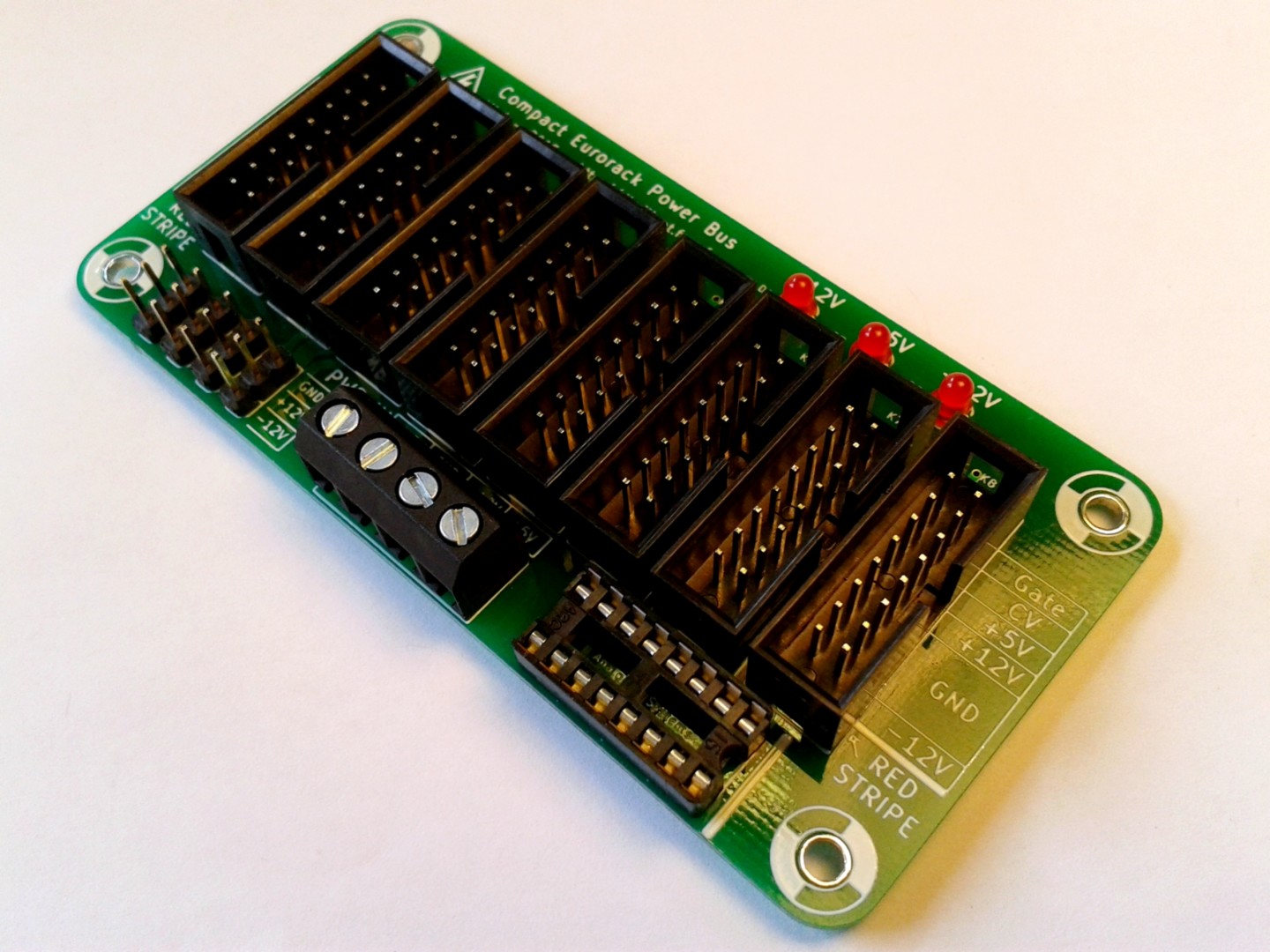
The 3 LEDs are now located on top of the circuit for an easier visualization.
And finally, all the passive components have been moved to the bottom side of the PCB and are now all SMD parts.

Downloads
- Schematic
- Compact Euro Bus 16 1.1 – BOM & doc 20160404
- Compact Euro Bus 16 1.1 – updated BOM 20180607
Links
- The Compact Bus V1.1 can be seen here: https://twspdotblog.wordpress.com/2017/11/18/keeping-the-iron-warm/
Hello,
meronics here from muffwiggler.
Very nice and compact design (compact-eurorack-power-bus) you got here, but where do you connect de caps?
Are they for reducing noise? What’s there function?
Best regards,
Marcos
Hello!
Thanks for your kind words.
The caps are SMD (1206, easy to solder) and located under the PCB, same as the LED’s protection resistors.
They are “bypass” caps (they offer a low impedance path for high frequencies, ie. reduce the high freq. noise), but they can be omitted because bypass caps are really efficient when located as close as possible to the noise source (high speed ICs, switching devices…).
Hope it helps 🙂
that’s a perfect explanation, thank’s a lot an and keep the good work, you have very nice and neat design’s, love it.
Marcos
Hi, David,
I just received the kit for your compact bus board. Thank you for the prompt shipping.
I didn’t notice the 16 pin dil when I ordered, but I don’t see it populated in any of the photos of your PCB.
What is the purpose for this socket?
Thank you!
Hi Steve!
Glad you got it fast. Sometimes, it takes weeks… Go figure!
The DIL socket is an Analogue Systems DIL-16 power connector.
Analogue Systems modules do not use the traditional Eurorack style boxed header connector. They use instead a 16 pin DIL socket.
If you do not plan to buy an Analogue Systems module, then, don’t bother soldering it.
And if you end buying one, you can also use an adapter AS to Euro.
See https://www.sdiy.info/w/Eurorack
Thanks, David!