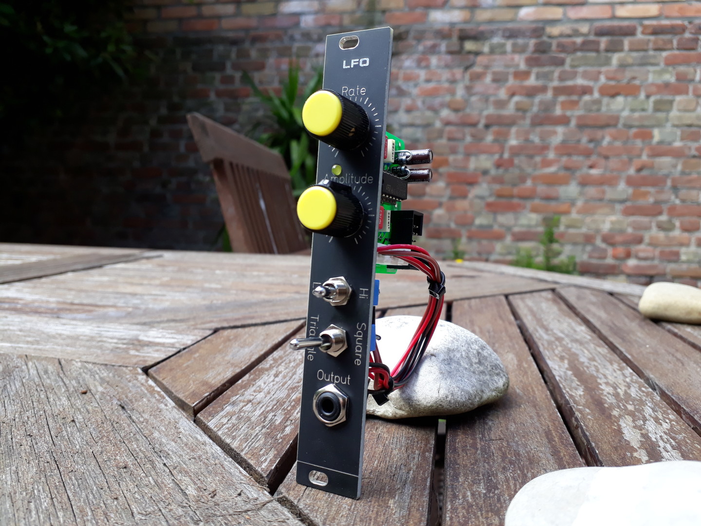
The Simple LFO is a… simple LFO module for your Eurorack system.
Two waveforms available: Triangle and Square wave. Adjustable amplitude and Low/High range switch.
It’s easy to build, easy to understand and maintain. Only easy-to-find through-hole components.
An updated and improved version is available!
Revisions
V1.4:
- Corrected an inversion in the LED circuitry, which prevented the LED to be lit as expected.
Simple LFO is available on Tindie!
Frequency Ranges
| Range | Lowest Frequency | Highest Frequency |
|---|---|---|
| LO | 2.5 mHz (0.0025 Hz) | 2.4 Hz |
| HI | 250 mHz (0.25 Hz) | 245 Hz |
Power requirements
| +12V | 10mA |
| -12V | 10mA |
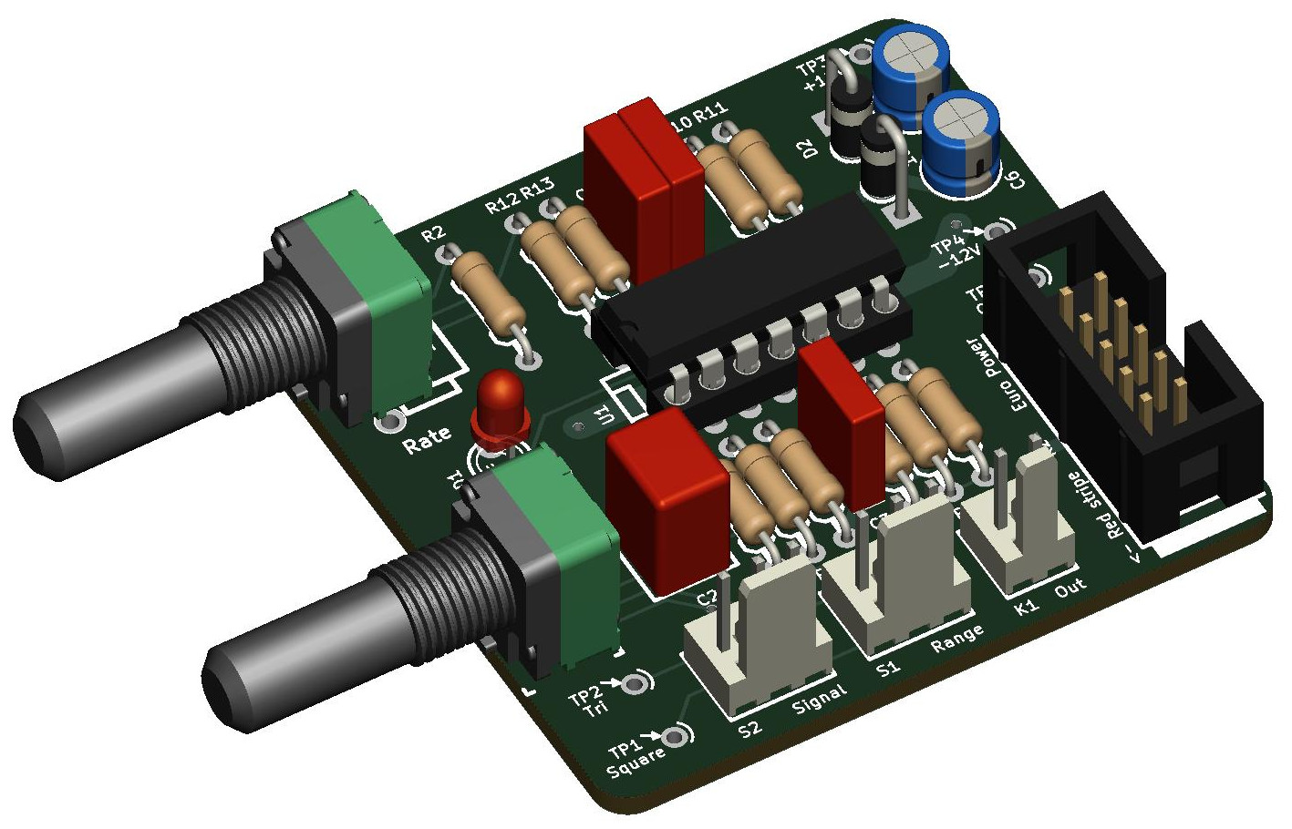
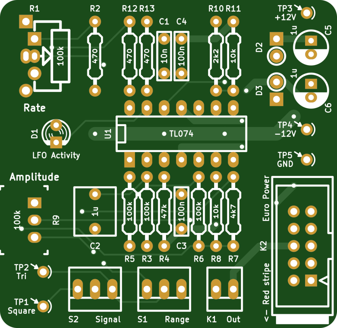
About the BOM
Many component values are not critical in the Simple LFO. It’s a robust circuit which can tolerate many experiments and modifications of the values.
The 2 input capacitors C5 and C6 can have any value between 1µF and 100µF. A common value is 10µF. One important thing is the minimal operating voltage of C5 and C6: it mustn’t go below 25V.
TL084 or TL074?
The TL08x and TL07x are interchangeable. They are pin-to-pin compatible, the voltage levels are identical.
The TL07x family is a lower noise version of the TL08x family.
However, the signal levels involved in synth modules is probably somehow immune to noise problems.
So feel free to use whichever version you want.
Potentiometers:
- https://synthcube.com/cart/synth-diy/parts/potentiometers/alpha-9mm-round-shaft-pc-mount-pots
- https://www.thonk.co.uk/shop/alpha-9mm-pots-right-angle/
- http://smallbear-electronics.mybigcommerce.com/alpha-single-gang-9mm-pc-mount/
- https://www.musikding.de/Alpha-Pots-9mm
Last minute details
About LED D1
The LED D1 is a dual LED (bi-colored). It is lit in one color for positive excursion of the selected waveform and lit in other color when the signal goes negative.
To address either one LED or the other, the polarity has to be reversed. For example, if pin #1 is positive and pin #2 is negative, the first LED is lit. If you reverse the voltage (pin #1 negative and pin #2 positive), the second LED is lit.
You can use a plain LED instead, and place it in any polarity you want, but it will be lit on only one excursion (either positive or negative) of the selected waveform.
About the diodes D2 and D3
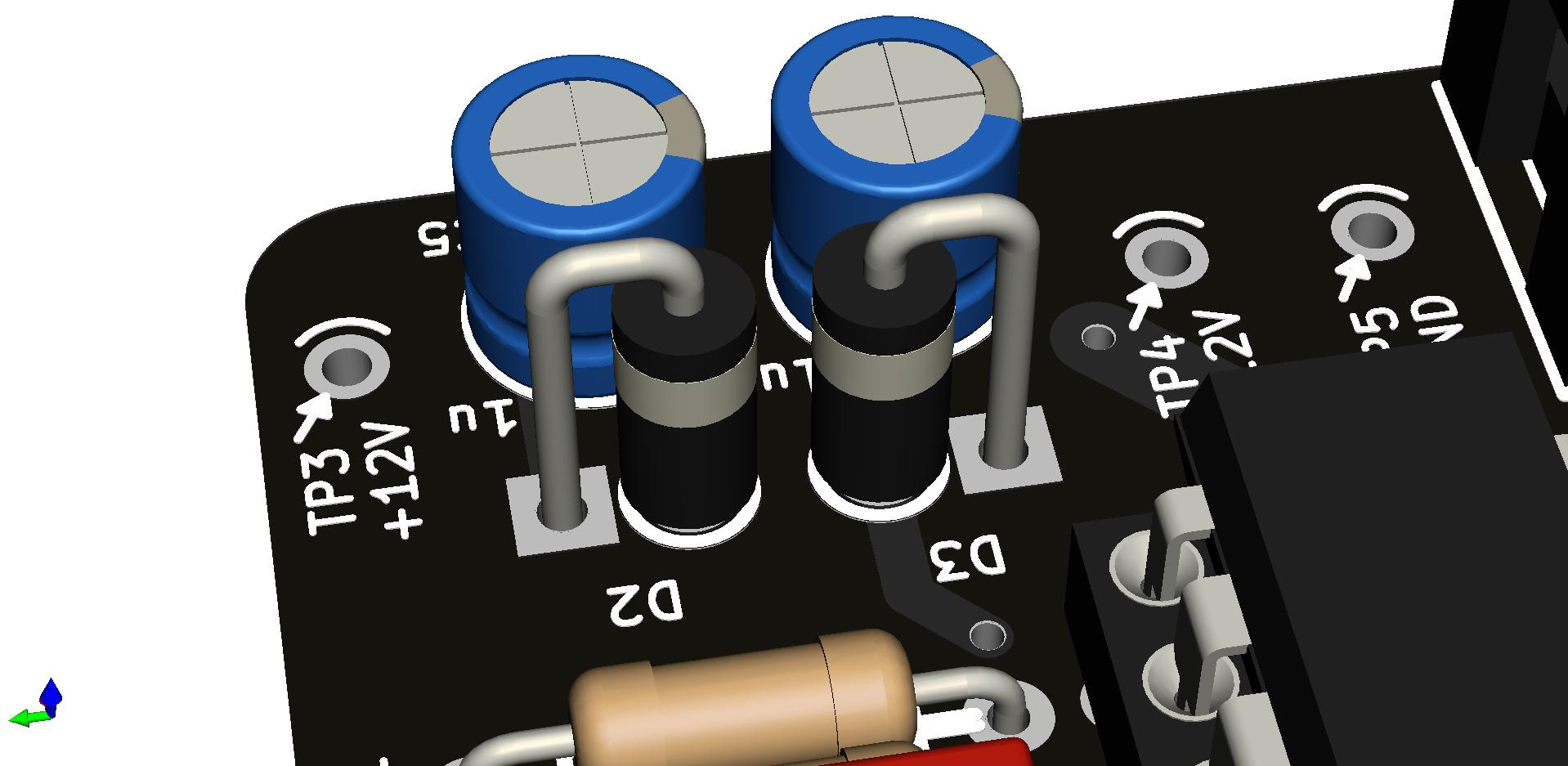
D2 and D3 are Protection Diodes: they protect against reversed voltages on the power connector. You can override the diodes with shortcuts (jumper wires or clipped legs from components).
They are to be mounted vertically, over the circle printed on the PCB, with their Cathode pin pointing Up. The Cathode side of the diode is the one with the white ring.
In other words, the Cathode must be connected to the square pad while the Anode is connected to the round pad.
The 1N4007 can be replaced by any 1N4000 diode (1N4004 etc) or by equivalent Schottky diodes 1N5817, 1N5819 etc. Schottky diodes have lower forward voltage.
Wiring

Documentation
- Schematics (lfo-1.4-20191103.pdf)
- Interactive BOM (lfo-1.4-ibom-2019-11-03)
- LFO 1.4 BOM & doc (LFO-1.4-BOM-doc-20201112.pdf)
Hi David,
Nice build! Currently designing my version of it in Easy EDA and had 2 questions:
1. Are diodes D2 and D3 necessary, given that you also have the electrolytic capacitors C5 and C6 in place?
2. In your schematic, the LFO activity LED diode is indicated as 2 LED’s. Shouldn’t it be one LED diode and one regular diode in parallel?
Cheers,
Pedja
Hi,
1. D2/D3 and C5/C6 have different purposes. The diodes are protections against reversed voltages on the power connector. The capacitors remove some ripples from the power DC voltages.
2. The LFO activity LED is either a single LED with nothing in parallel or, as shown in the schematics, a double LED, (two colors in a single case), to show the positive/negative alternances of the output signal. A single LED lits only on one alternance only. I personally think a dual color LED reflects more what’s happening.
Cheers
Hi there.
When are you going to sell these again. Tindie is out of stock 🙁
Hey, I put back in stock some LFO kits and PCBs on Tindie.
Just bought one, thanks.
Those 9mm pots were hard to get hold of at a decent price, but if anyone is having similar problems I found them at Thonk for just over £1 each….
Hi,
First of all thanks for sharing. After analysing the schematics I was left with some questions regarding the the LFO activity circuit…shouldn’t the inverting input of that opamp connect directly to the output, and not to the intermediate point after the resistor and double Led? Why is it connected in this way? Could you please explain it to me?
Thanks in advance.
Hi,
Located in the feedback loop, the LED is current driven instead of voltage driven. The amount of current is determined by the R value.
Iled = Vin / R
Here’s a simulation comparing several circuits: https://tinyurl.com/y5ycevu7