This is an update of the 606 Bass Drum clone: version 1.4
Revisions
V1.2:
- Addition of an op-amp buffer output and correction of the trigger circuit (PNP instead of NPN for Q2)
V1.3:
- R10, R12 and C5 have been removed.
- R22 connector has been replaced by a resistor footprint. (47k is fine).
V1.4:
- Removed R10
- Added 1k Output protection resistor R10
- Modified Accent input circuitry
How it works
The 606 Bass Drum uses a double Twin-T damped oscillator. Each oscillator is tuned to a different frequency. The output of each oscillator is mixed together and the “Tone” potentiometer sets the amount of signal from each oscillator to be fed to the output buffer.
The output buffer amplifies the signal to Eurorack compatible levels (+10/-10Vpp).
The input is common for both oscillators.
The input circuitry converts any Gate signal and negative excursions into Trig signal. Expected Trigger level is +5V.
The Accent potentiometer and its associated input jack allow you to change the volume. If the jack connector is plugged, the potentiometer is bypassed.
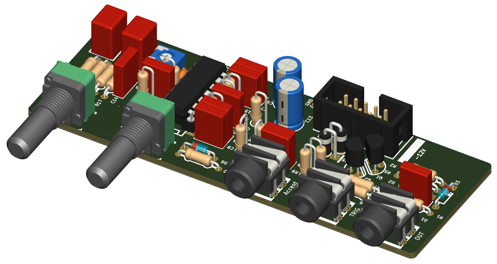
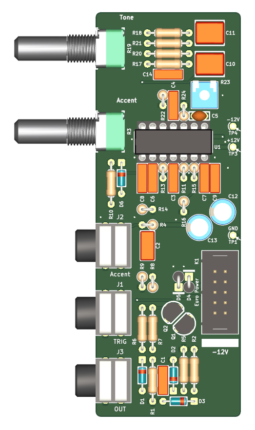
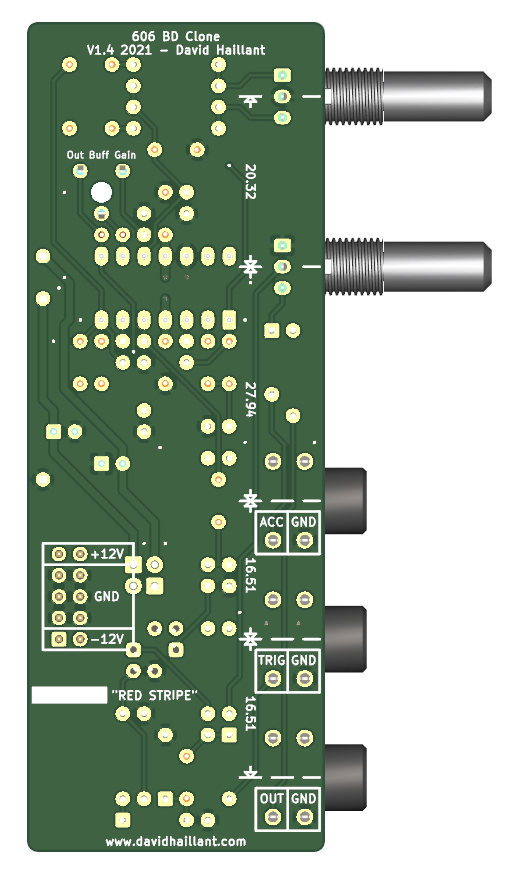
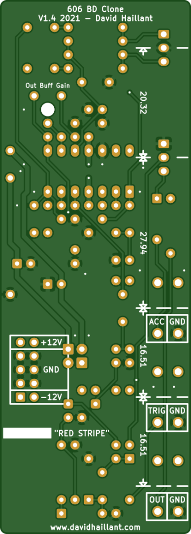
Gallery
Build instructions
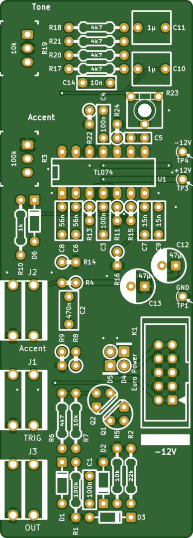
The build process is straightforward. I recommend to refer to the Interactive BOM (It doesn’t represent the components in a particular order though).
It is easier to start by soldering the smaller parts (diodes, resistors) first and finish with the bigger ones (capacitors, etc).
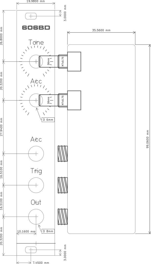
I also recommend to first tighten the jacks and the potentiometers to the front panel before soldering them.
Most of the components values are written down on the silkscreen. Those values are, to date, correct.
The resistors have no polarity to respect.
Some are mounted either horizontally or vertically. The Interactive BOM lists them separately but they are the same components, and same value.
The diodes are polarized. Please follow the silkscreen marks.
Diodes D4 and D5 can be omitted and replaced by simple jumper wires, but they help protect your module against reversed power supply.
They are mounted vertically. The cathode (the white ring) is up.
The capacitors are divided in two categories: the ceramic or “plastic” ones, which are not polarized, and the Electrolytic (or aluminum) ones, which are polarized.
Only C12 and C13 are aluminum caps and must be carefully oriented. Watch for the longest pin (the positive side). The white band on the capacitor body shows the negative side.
IC U1 is polarized. Pin #1 faces the front side.
The output buffer has a trimmer potentiometer (R23) for setting the output amplitude. Turn Clockwise to increase the output, CCW to decrease it. Adjust until distortion disappears (the maximum amplitude is when “Tone” potentiometer is set on middle position).
R23 is a 10k, 6mm trimmer. This one at Mouser should be fine.
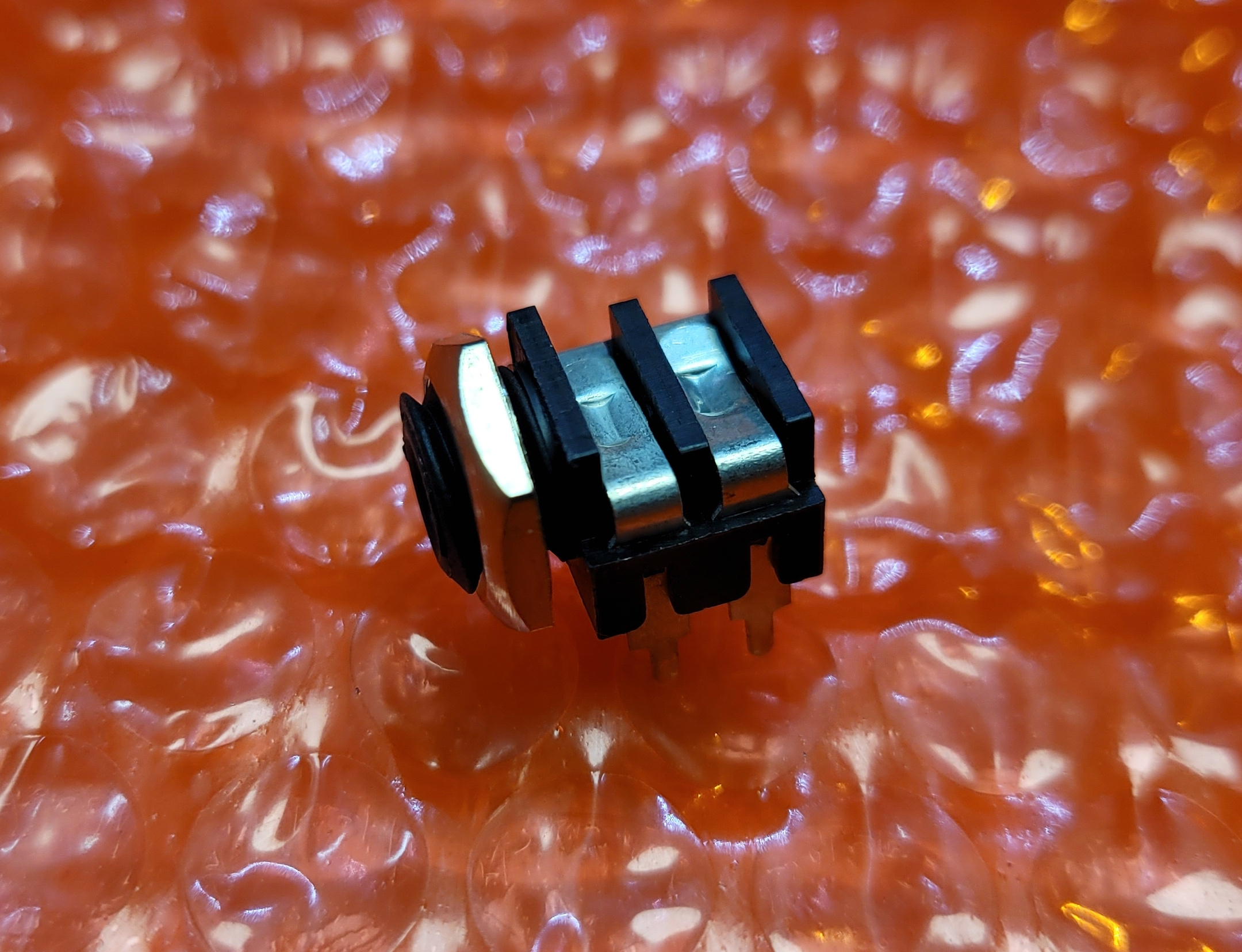
Jack connectors
The Jack connectors are Cliff CL1384. This kind of Jack socket requires mono jack plugs and mono cables.
Suggested Mods
You can remove D3 and replace it by a jumper.
R24 value can be lowered to 2.2k or 4.7k to increase the output amplification.
Documentation
Hi David. I love this module, but even with R24 at 2.2k it’s still not loud enough for me. I’m running it through a VCA to boost it but could I lower R24 further? and how much lower?
Also, what does the D3 mod do?
Many thanks. Lovin your work!
Hello Martin,
Yes, you can replace R24 by a wire, so that the amplification gain will be set only by potentiometer R23.
(You can also increase value of R22 to 100k for example, it will reduce the effect of the voltage divider R20&R21/R22).
D3 is not necessary and can be not populated (bypassed).
D3 is redundant because of Q1. (The Gate-to-Trig circuit was borrowed from another module and I missed the fact that D3 was redundant here.)
Hope it helps!
Excellent! Thanks very much.
Martin
Just done the mod – replaced R24 with a piece of wire – and it’s much much better. I really think you should include it as an option in your build instructions. Thanks a lot.
Hi David,
I’m building my second David module and just now ran into the first unclarity. I wasn’t able to source the Cliff CL1334 mono jacks and had to Macgyver some other jacks in there. Is the 12V passing R4 always connected to the Accent input, or is the connection cut whenever a cable is plugged in?
Thanks for making this awesome module.
Kind regards
ThomasC
Hello Thomas!
Yes, the 12V from R4 enters the Accent circuitry only when a jack plug is not inserted.
On the other hand, when a cable is connected, it’s the voltage coming from the cable that goes into Accent potentiometer instead.
On the schematics, J2 has 3 pins: T (Tip), TN (“Not” Tip) and S (Sleeve). R4 is connected to TN.
When no cable is inserted, TN and T are shorted together. T voltage is then equal to TN voltage.
When a cable is inserted, T and TN are separated. T is then only connected to the Tip of the jack plug.
Please let me know if there are still unclarity with this.
Kind Regards
David
Hi, David:
I love this project, thanks for sharing the schematics and BOM list, I have a question, can I use Drum Gate output on Arturia BeatStep Pro to drive this BD drum work?