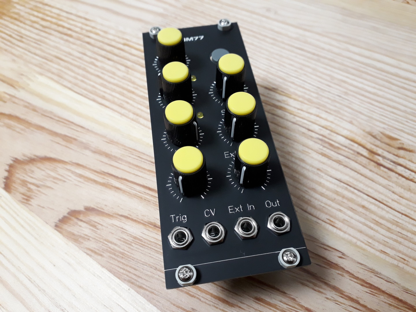
Things are going well with the DM77. A new revision of the PCB is on my desk, ready for some tests.
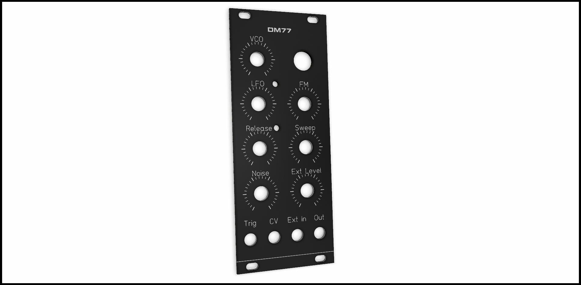
In the meantime, I’ve just received the new 10HP Front Panel. It’s cute in black!
This documentation concerns a prototype version of the DM77 and is here only for reference.
Please, read instead the documentation and assembly guide for DM77 V1.0.
The 0.4b PCB needs some mods.
Gate/trig input
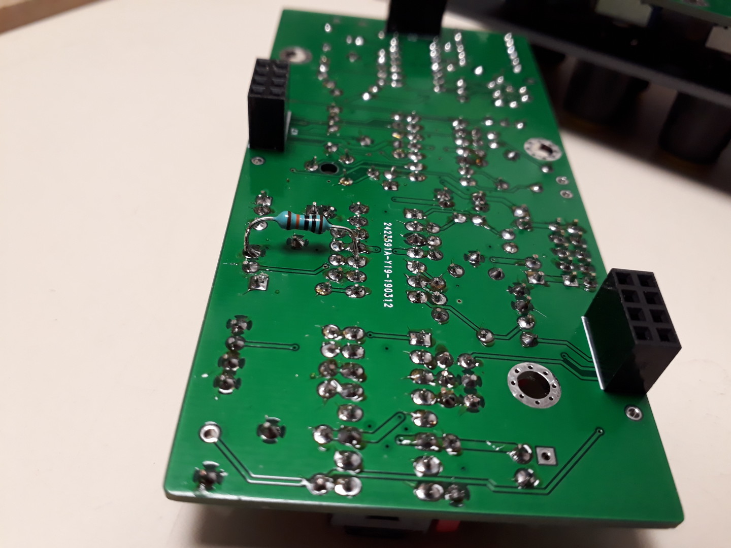
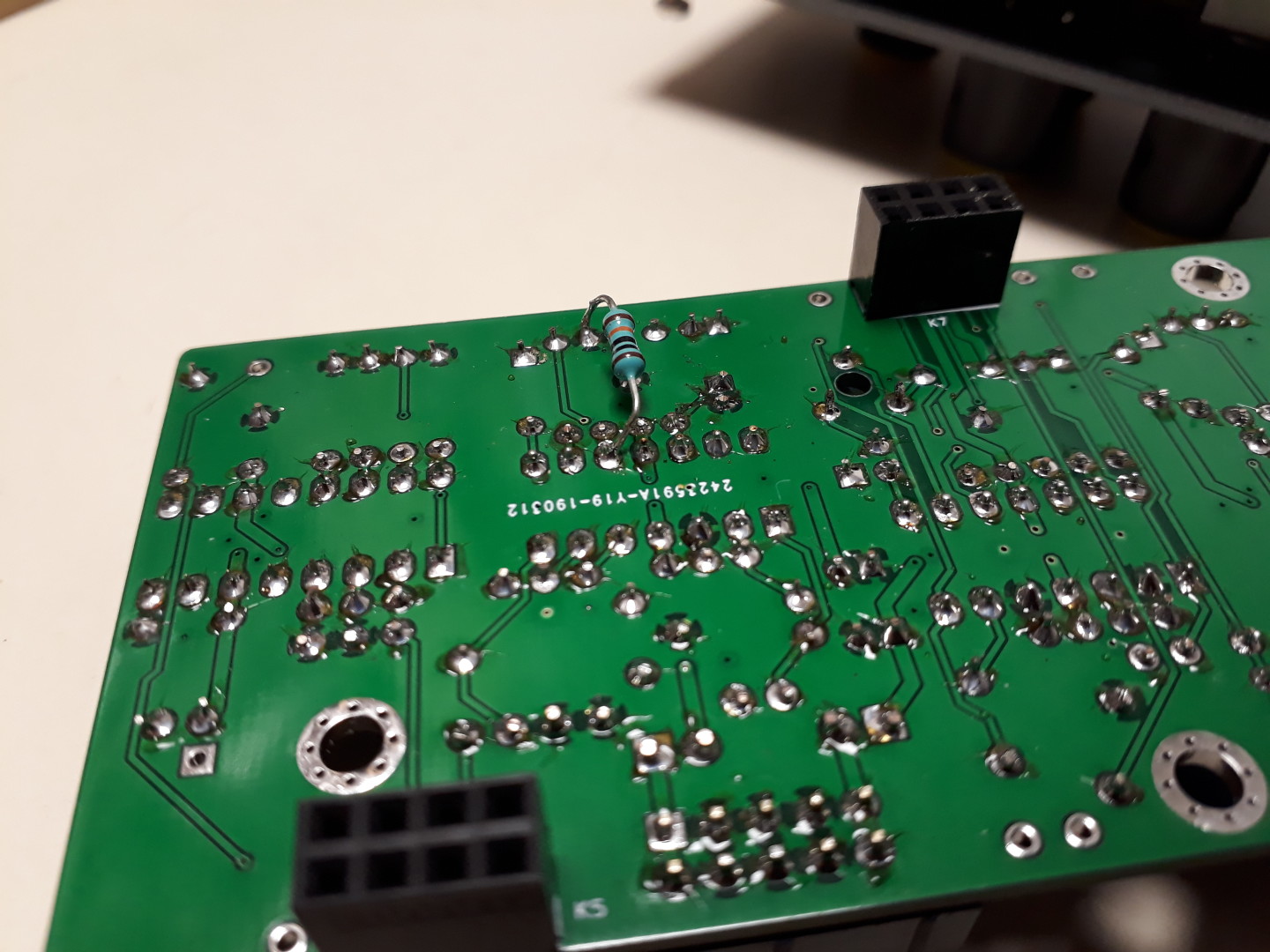
Opamp U1C has some problems with input impedance (picked up noise). R2 should be located on Bottom PCB.
Add a 100k Resistor as shown below:
Noise volume
The noise source can be too strong compared to the VCO. Consider using a 100k Ohm for R19.
LEDs connections
The LEDs work on 0.4b but not as I planned.
First, D4 (Gate) stays slightly lit even when no gate or trig input. The reason is R9 is connected to -12V where it should be connected to 0V (“GND”). Solder R9 on only one pad and connect the second lead to Ground.
D5 (LFO) has the same behavior. In 0.4b, R16 is tied to +12V and D5 connected to LFO Square signal. In 0.5 I changed connections this way: R16 is driven by LFO Square signal and D5 is tied to Ground on its cathode.
MORE to come!
Downloads
- 0.4b Schematics: dm77-0.4b-20190606.pdf
- Interactive BOM: dm77-0.4b-ibom-2018-03-24