Just a quick update on the Simple LFO circuit. I was playing with LTSpice for some forthcoming modules when I decided to simulate the Simple LFO. The idea was to compare the simulation to a real working circuit.
And it was a good idea. Here’s the result of the simulation:
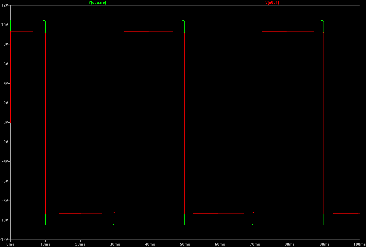
In red, the current used waveform. In green, a way better square waveform. (Click to enlarge)
The red waveform is currently used as the “square” output in version 1.1. This signal is obtained between R3, R4 and R5. I must confess, it’s far from perfect. The signal isn’t “flat” on high and low levels. There’s a difference of almost 0.5 V between the start and the end of each positive and negative pulses.
With my equipment (an old CRT analog scope) I was unable to detect that little instability.
Actually, the (real) square output should be retrieved from another point, directly at the opamp output. Furthermore, at that point, the waveform amplitude can be even greater. Up to +10/-10 V.
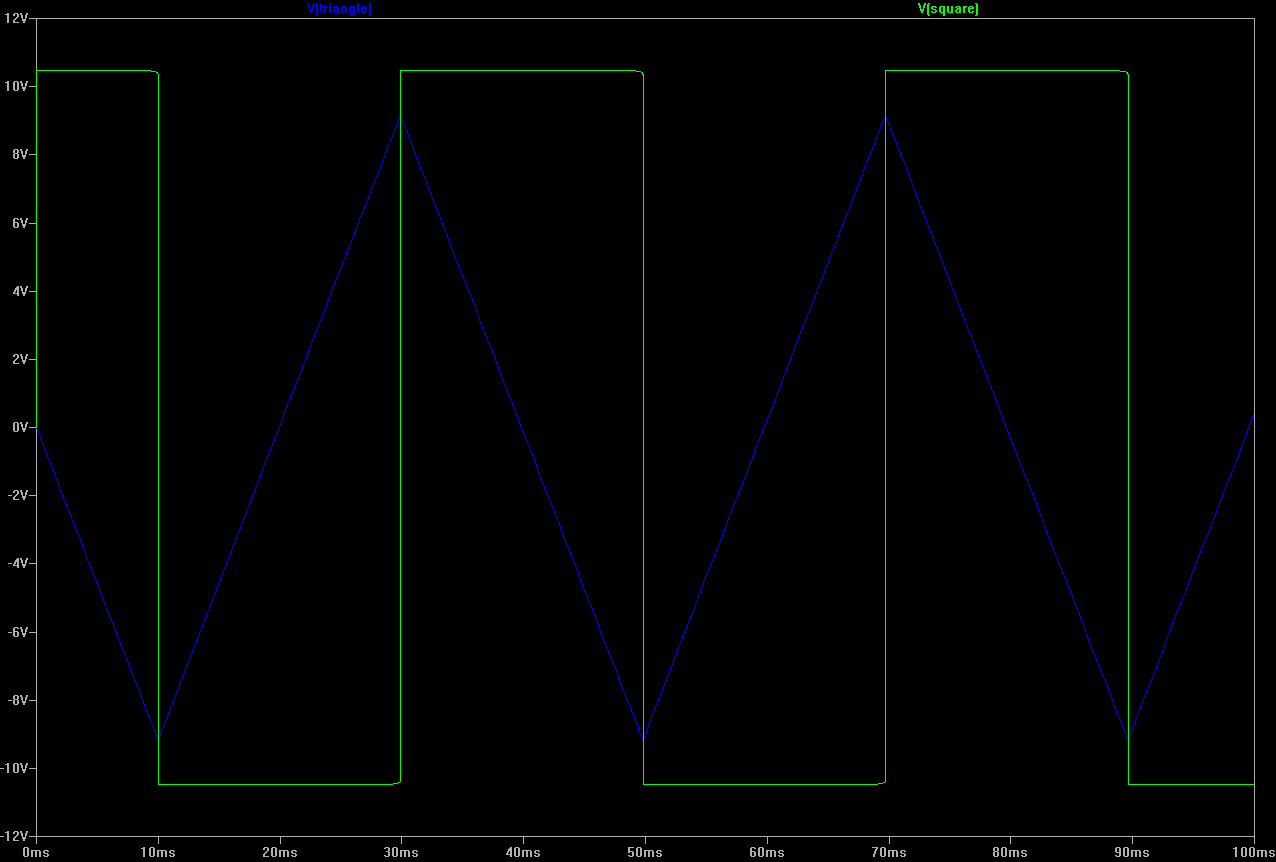
As for the triangle waveform, it’s perfectly fine.
I changed some values anyway:
- R7 (R4 in Spice schematics) is now 1k (was 4k7)
- R8 (R5 in Spice) is now 100k (was 10k)
With these new values, the triangle waveform amplitude is increased to +9/-9 Volts.
Of course, this is only a simulation and the mods need to be confirmed by some real tests, with real components.