The Bus number 18 is here!

This bus is one of several variants available, each with different connector counts to suit various case sizes. View all power bus options
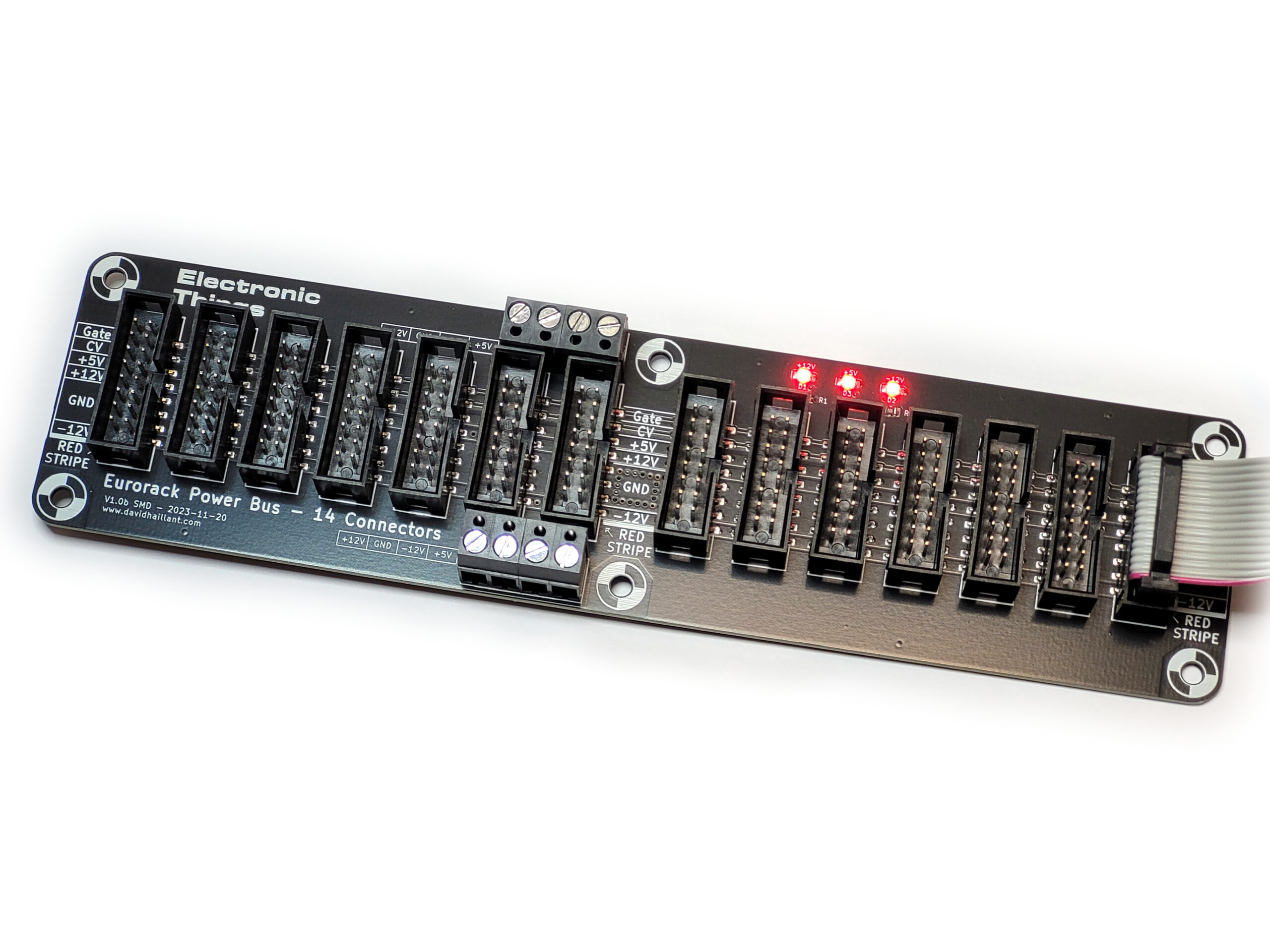
The Bus 18 is a high-density power distribution board for Eurorack synthesizers, designed to supply up to 18 modules.
Key Features
- Expanded Connectivity – Four additional connectors compared to the Bus 14, without increasing board size.
- Flexible +5V Supply – Includes an onboard linear regulator for +5V (optional, can be bypassed for PSU-powered +5V).
- Universal Placement – Fits in skiffs, travel cases, or large racks—ideal for high-density systems.
- DIY Friendly – All the components are Through Hole (THT).
Technical Specifications
Dimensions
- Length: 20 cm (7.87″)
- Width: 5 cm (1.97″)
Power Input

Screw terminal connectors (top and bottom)
- Compatible with most Eurorack PSUs
- Allows daisy-chaining multiple buses
3 LED status indicators (one per rail: +12V, -12V, +5V):
- Confirm voltage presence
- Verify correct polarity
Module Connections
18 × 16-pin Eurorack headers
- Keyed design prevents reverse insertion (but always verify!)
- Standard Eurorack cable compatible
+5V Power Options
The Bus 18 supports two methods of supplying +5V to your Eurorack system:
- Onboard +5V Generation
The bus board includes a +5V regulator circuit to generate +5V from the +12V rail. - External +5V from Your PSU
If your power supply already provides a +5V rail, you must bypass the onboard regulator and omit these components during assembly:- The +5V regulator (U1)
- The two diodes (D4 and D5)
- The two capacitors (C4 and C5)
Feed the +5V into either the top or bottom screw terminal (the board accepts it on either side).
Important Notes
- Do not mix methods: Use either the onboard regulator or external +5V, never both.
- Check PSU capacity: Ensure your power supply can deliver enough current for all connected +5V modules.
Build your bus
As always, start by soldering the smaller parts (resistors and diodes, then the regulator).
Then progressively solder the bigger and taller ones.
Using that method, it’s easier to solder the components aligned and flush to the PCB. Simply place the components on the PCB, flip it over and let it rests on your workbench. Then solder only one pin per component. Flip the board back, check twice that the orientation and the alignment are correct. If so, solder the remaining pins.
Diodes and LEDs are polarized. The square pad is the Cathode.


so far I think I have ordered 7 of these buses I will only use these in my case builds absolutely perfect for cases , I may try a 26 port unit in my next build , build time 30 min to completion. again quality product