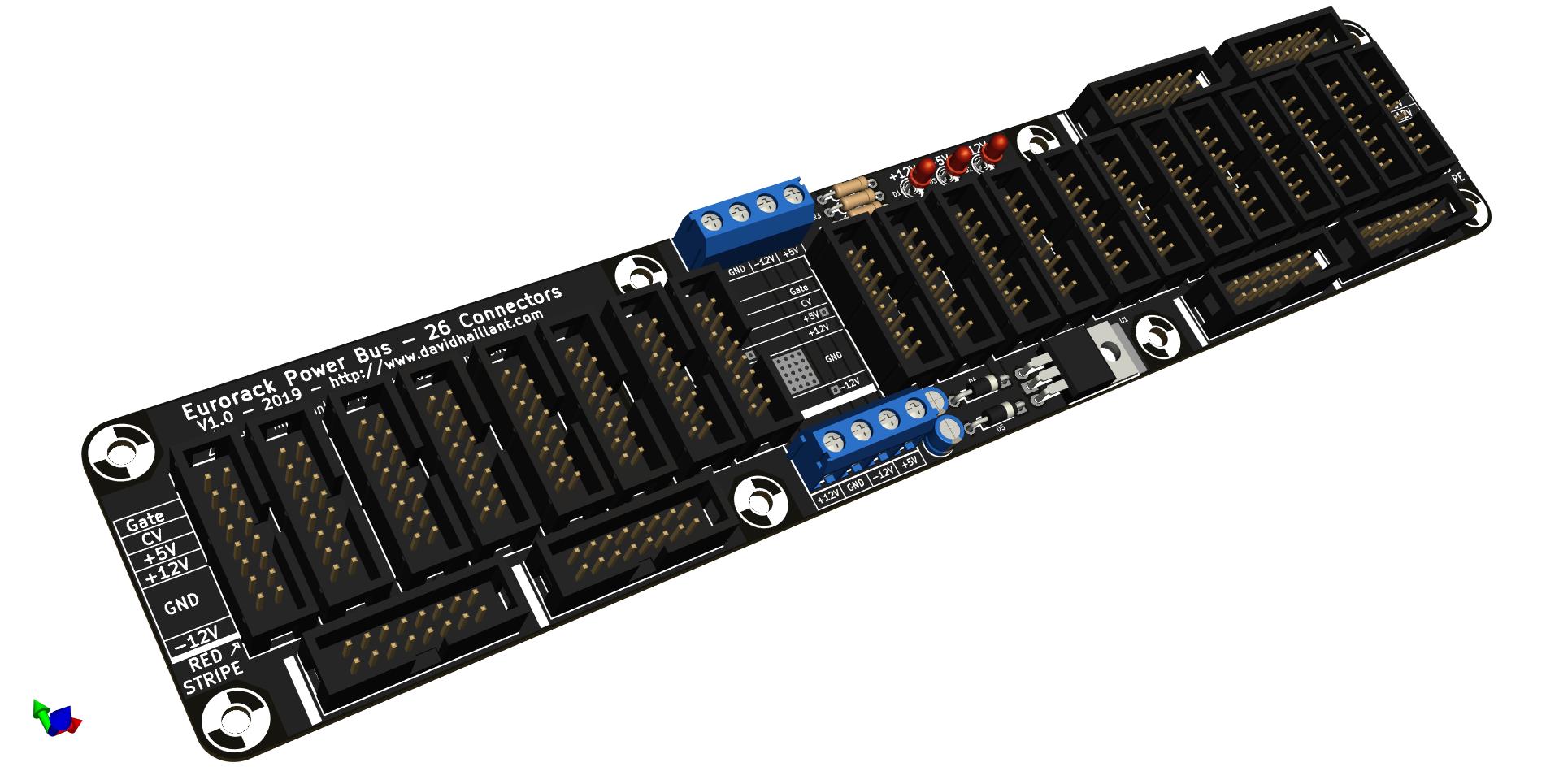
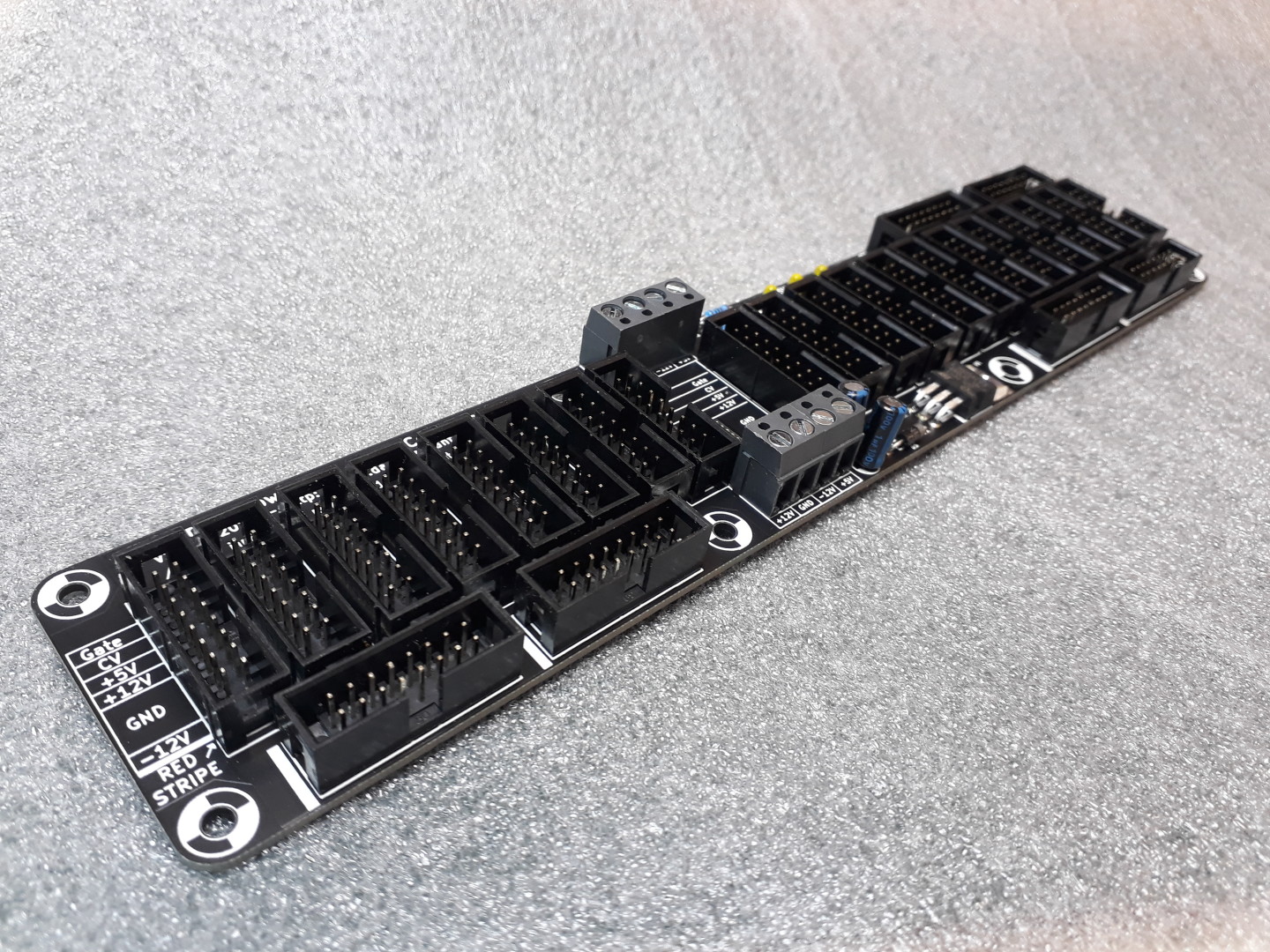
This is the Eurorack Power Bus on steroids: 26 connectors on a 25cm x 5cm board!
There are different buses available, with various sizes and number of connectors.
So, it’s an upgraded version of the classic Eurorack Power Bus.
This power distribution board for Eurorack synths will easily power up to 26 modules. With on-board generated +5V rail (using the +12 V rail).
Place the Bus Board in the back of your Eurorack Skiff or your monster case and plug in it your modules.

The bus is 25 cm long, 5 cm wide (9.84″ x 1.97″).
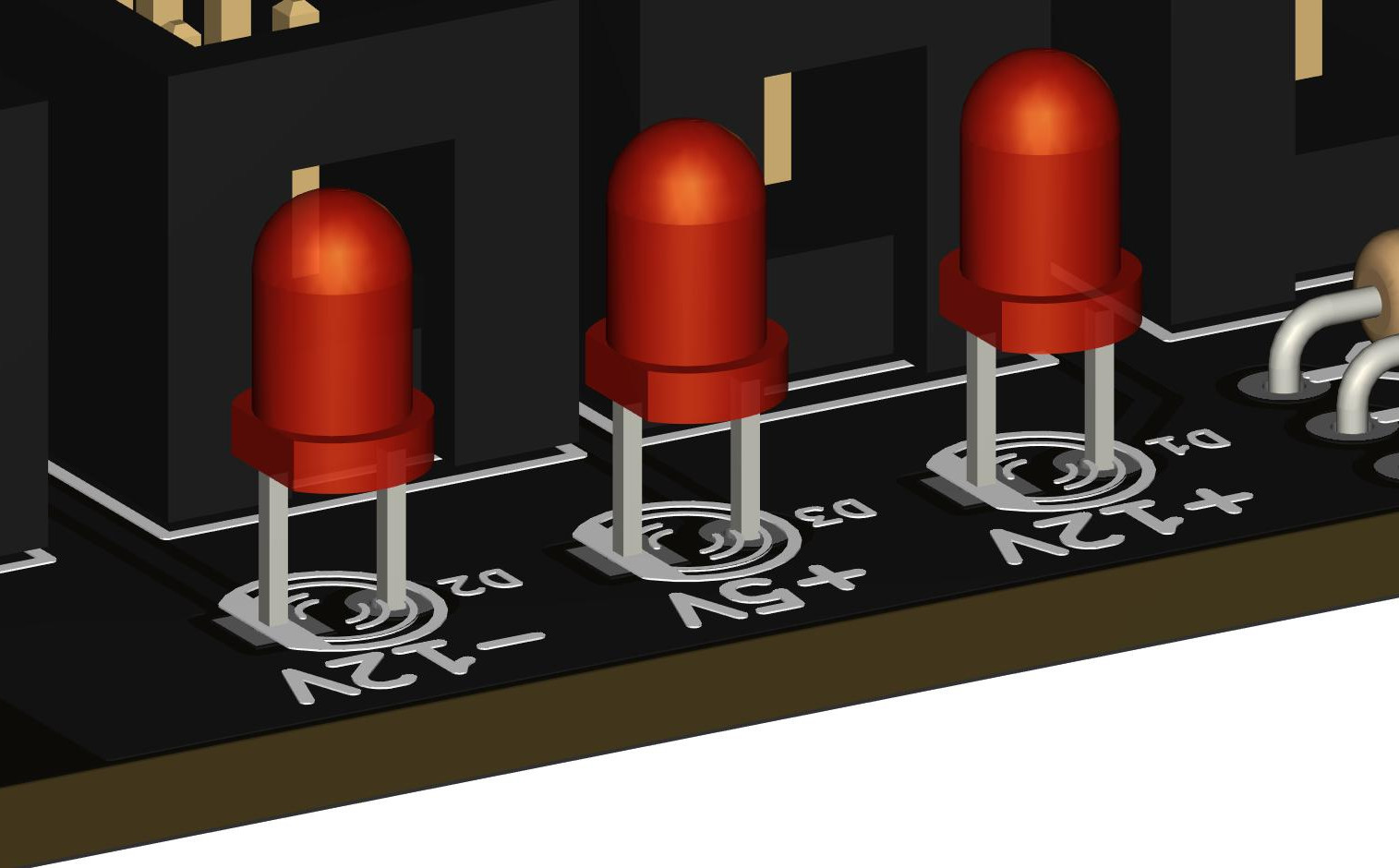
There are 3 LEDs for visualizing the 3 Voltage Rails. This LEDs shows you if there’s energy on the rails, and if the polarities are correct.
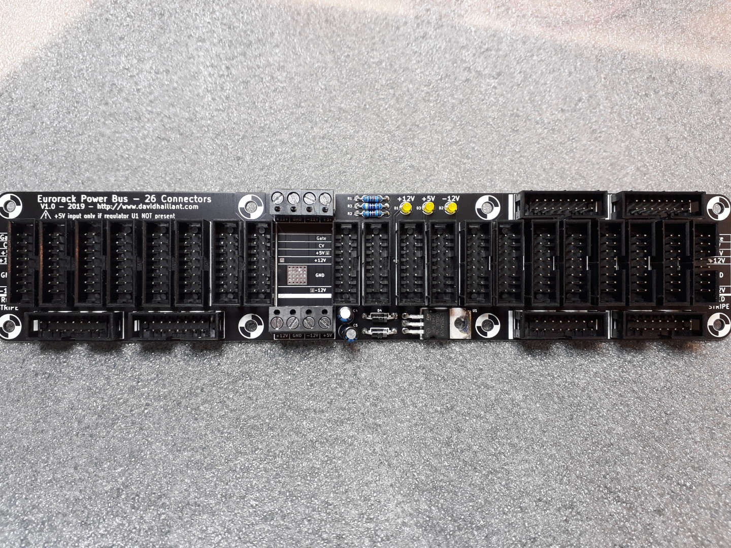
Input is done through a Screw Terminal connector.
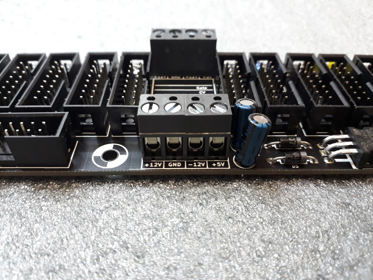
Screw Terminals are very versatile. You can connect easily to the Bus Board any Power Supply. You can replace it by any 5.08 mm pin pitch connector.
There’s one connector on top and one on bottom side of the bus.
HE-10 Connectors are keyed: they decrease the risk to connect the modules in wrong polarity.
But, you absolutely need to check your wiring twice before powering the bus!
Read the modules’ manual and documentations. Check the cable. Check again.
Check Again!
Build your bus
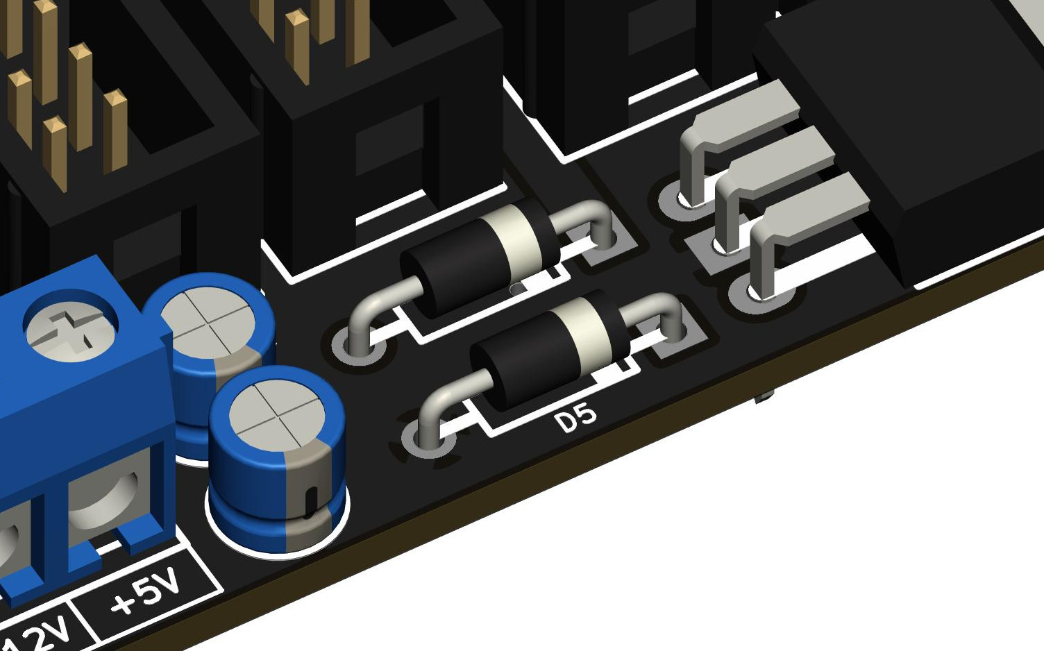
As always, start by soldering the smaller parts (resistors and diodes, then the regulator).
Then progressively solder the bigger and taller ones.
Using that method, it’s easier to solder the components flush to the PCB. Simply place the components on the PCB, flip it over and let it rest on your workbench and then solder only one pin per component. Flip it back, check twice that the orientation and the alignment are correct. If so, solder the remaining pins.
Diodes and LEDs are polarized. The square pad is the Cathode.

What is anode /kathode on the pcb of the leds?
square = – , round = + ?
To answer your question, I added some details in the documentation above.
Hope it makes sense.
(The cathode is the square pin.)
You mention that the board will generate +5v on its own, but there’s definitely an input header for +5v.
Should we _not_ be connecting +5v to that input?
Also, is it possible to connect power using one of the 2×8 HE-10 connectors, or does power need to come in through the screw terminals?
Hello Stephen,
If you have a PSU that can generate the +5V and you want to use it, then you can plug it into the bus. In this case, the on-board regulator mustn’t be installed.
On the other hand, if you don’t have a PSU that can generate the +5V or you don’t want to use it, then simply do not connect the +5V to your PSU and use the on-board regulator instead.
You can’t have the regulator and at the same time input +5V from a PSU. It will damage something.
Also, even if it’s possible to connect your bus through a ribbon cable on any HE-10 connector, I recommend to input power through the dedicated input connectors for better performance.
It is recommended to use thick wires to connect the PSU to the buses.
Let me know if you need more details.
David
Hey David,
Thanks for the response.
One more question: Do I need to connect both input connectors, or are two provided for convenience?
Hey,
No need to connect both. You can use the second for chaining for example.
Hi there. I have a uZeus power supply and looking to use that with one of your 26 buses.
Can I check the connection would be a case of stripping back and exposing the relevant cables from the 16pin ribbon cable and screwing those into K101 ? And can two boards be connected by hooking K101 of one to the other?
Also would duty have to paid for the UK now we’re no longer in EU 🙁
Thanks
Ric
Hi Ric,
The easiest and quickest way to connect your µZeus to the bus would be to use a regular 16-16 pin cable and connect it somewhere near the middle of the bus board for best power distribution. Even better if possible, use two (or 3?) 16-16 cables!
No need to damage a ribbon cable to let power enters at K101. Power can also be applied at any 16 pin connector (even if it’s not the best practice). But in your case, the best solution probably!
And if you want to connect two bus boards, you could use one 16 pin ribbon cable from µZeus per bus board, then connect the bus boards together through K101 (or K102) with thicker cables to lower impedance.
That’s perfect thanks. I current have 3 ribbons coming from the uZeus.
Lastly do you know if any duty will be charged when it gets to the UK?
About the duty and the customs policies in general, I have no idea, sorry.
But they probably charge only bigger shipments…
Cool, thanks so much. An order shall be placed 🙂
Last question, if I connect the uZeus directly to the board then I should leave the regulator off the build as it won’t need to generate the 5v itself, right?
Yes, as the uZeus provides the +5V itself, do not populate the following: U1, C4, C5, D4 and D5.
Last question. If I do connect the uZeus with directly using ribbon cables, I need to leave the regulator of of the build as it won’t have to generate it’s own 5v, right?
Oops sorry, just saw your response. Thanks and please ignore me 🙂