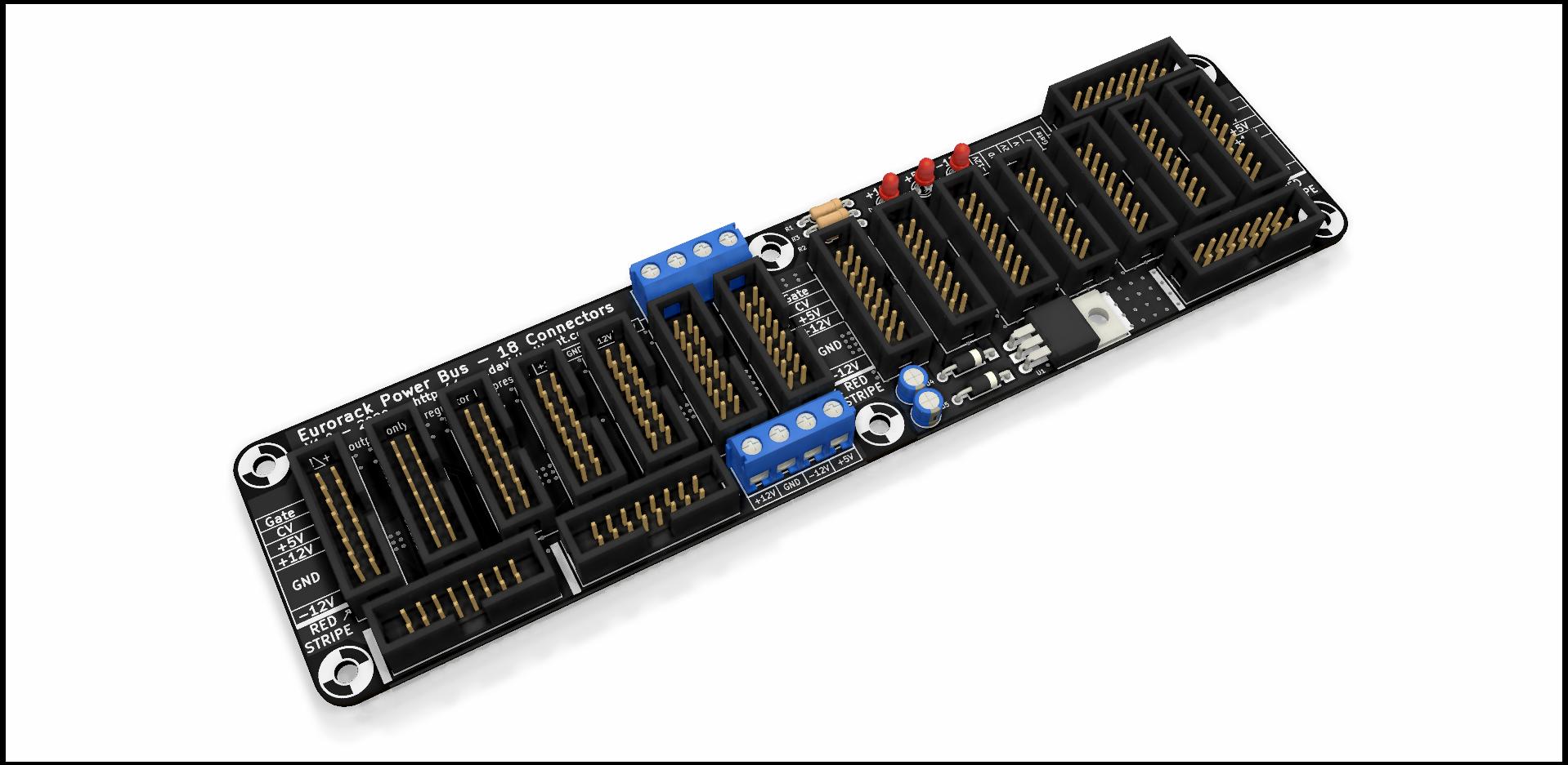
The Bus number 18 is there!
There are different buses available, with various sizes and number of connectors.
It’s a slightly modified version of the Eurorack Power Bus – 14 with 4 more connectors.
This power distribution board for Eurorack synths will easily power up to 18 modules. With on-board generated +5V rail (using the +12 V rail).
Place the Bus Board in the back of your Eurorack Skiff or your monster case and plug-in it your modules.
The bus is 20 cm long, 5 cm wide (7.87″ x 1.97″).
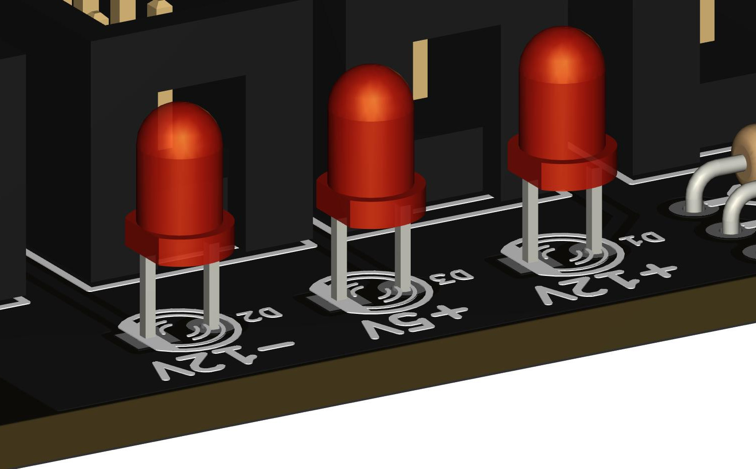
There are 3 LEDs for visualizing the 3 Voltage Rails. This LEDs show you if there’s energy on the rails, and if the polarities are correct.
Input is done through a Screw Terminal connector.
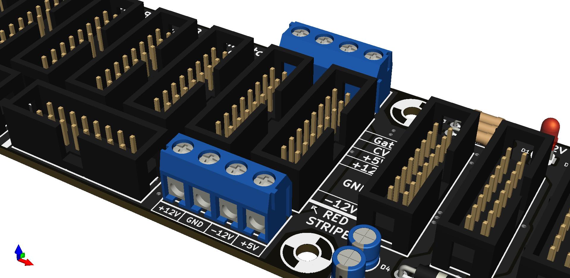
Screw Terminals are very versatile. You can connect easily to the Bus Board any Power Supply. You can replace it by any 5.08mm pin-pitch connector.
There’s one connector on top and one on bottom side of the bus.
HE-10 Connectors are keyed: they limit the risk to connect the modules in wrong polarity.
But, you absolutely must check your wiring twice before powering the bus!
Read the modules’ manual and documentations. Check the cable. Then check again.
Check Again!
Build your bus
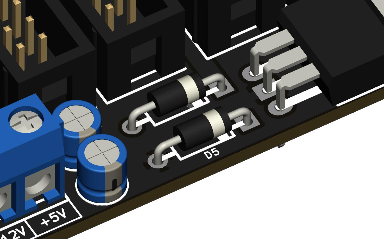
As always, start by soldering the smaller parts (resistors and diodes, then the regulator).
Then progressively solder the bigger and taller ones.
Using that method, it’s easier to solder the components aligned and flush to the PCB. Simply place the components on the PCB, flip it over and let it rests on your workbench. Then solder only one pin per component. Flip the board back, check twice that the orientation and the alignment are correct. If so, solder the remaining pins.
Diodes and LEDs are polarized. The square pad is the Cathode.