The passive OR module is the perfect tool to merge gates and triggers from multiple sources (e.g., sequencers, LFOs, clocks, dividers, or other modules) to create complex rhythmic patterns.
The module is extremely simple, yet very useful in any setup.
Typical Use Cases:
- Multiple clock sources to generate poly rhythms. Perfect combination with UC Clock Divider!
- Trigger an envelope generator from different sources (a sequencer and a manual gate or MIDI event)
- Crude mixing, with artifacts, of audio signals (listen to audio demo below).
Mixing two audio signals through Passive OR:

Key Features
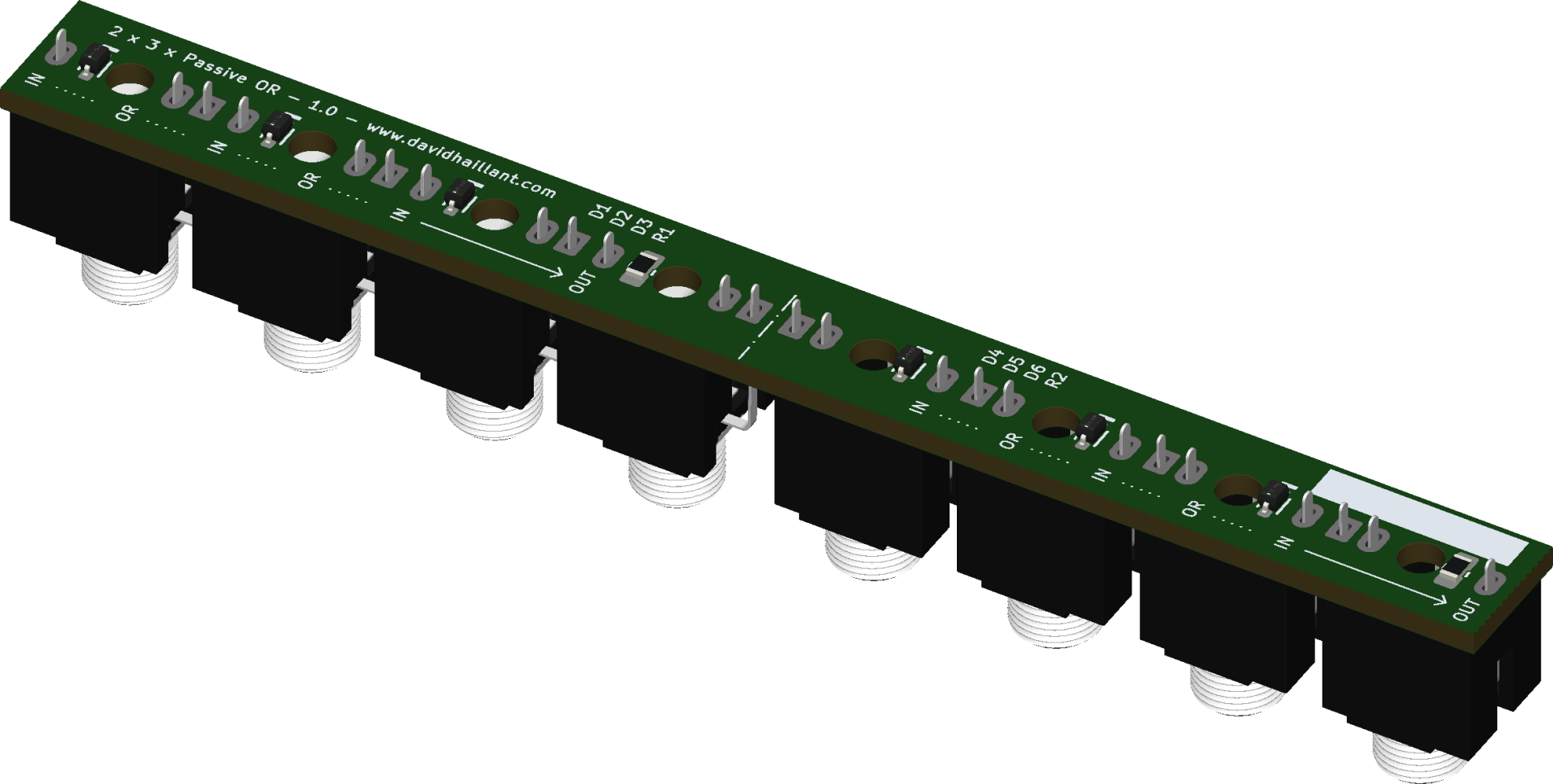
Passive Design:
- The module does not require external power, making it easy to integrate into any setup.
- It relies on diodes to perform the OR logic function, which is simple and efficient.
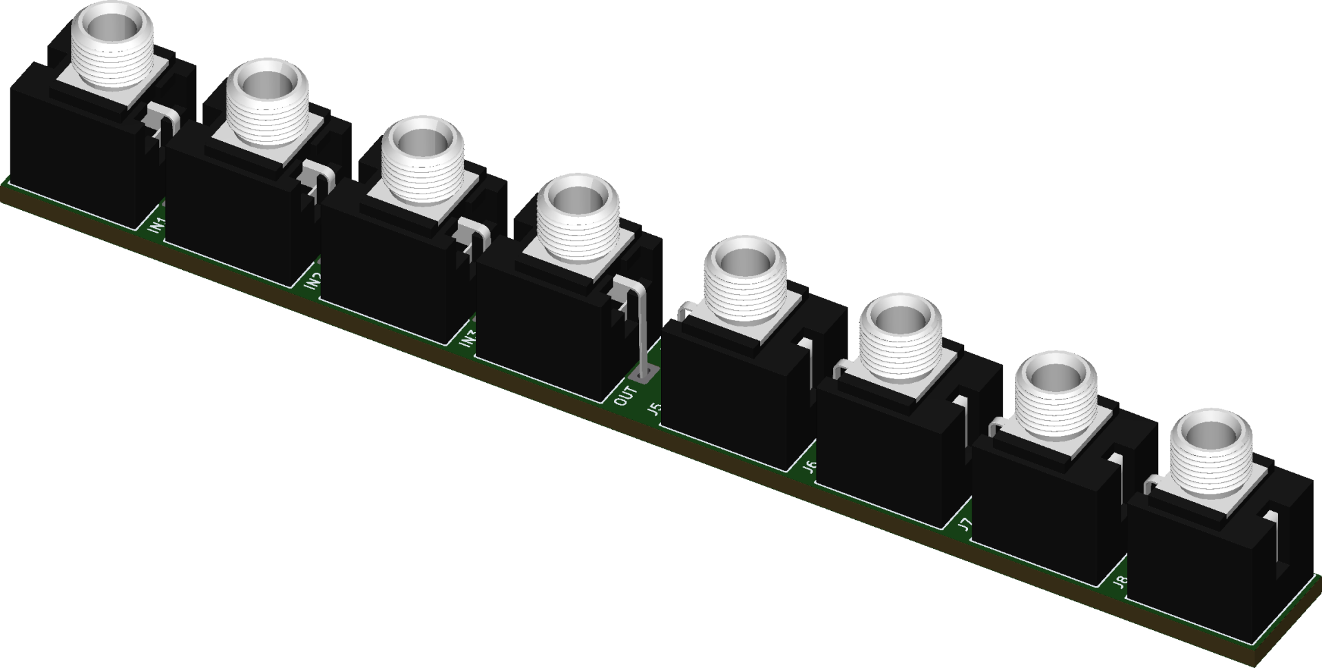
Compact Size:
- The module is only 2 HP wide and less than 15 mm deep, making it ideal for systems with limited space.
The simplicity of the module comes with some limitations:
- No signal amplification (output voltage is lower than input due to diode voltage drop).
- Limited fan-out (ability to drive multiple inputs).
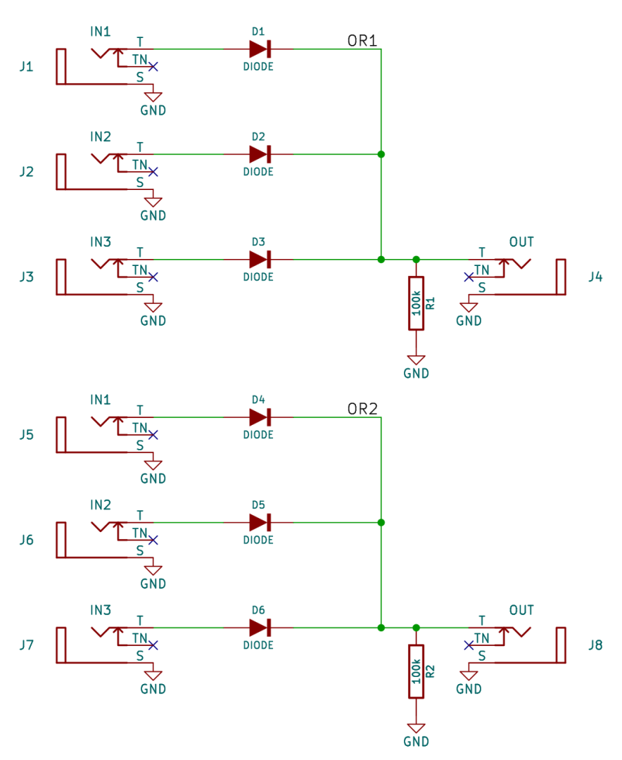
Theory of operation
A diode logic OR gate is a simple digital logic gate that uses diodes to perform the OR operation. The OR gate outputs a high signal (logic 1) if at least one of its inputs is high. Here’s how a diode-based OR gate works:
Each input is connected to the anode of a diode.
The cathodes of all diodes are tied together at a common output node, which connects to the output jack.
A pull-down resistor (100kΩ) is connected between the output node and ground to ensure a defined low state when no input is active.
When an input is HIGH (e.g., +5V or +10V gate signal):
- The diode becomes forward-biased (anode voltage > cathode voltage).
- Current flows through the diode, pulling the output node up to the input voltage minus the diode’s forward voltage drop (~0.7V for silicon diodes).
- The output signal will be ≈ input voltage – 0.7V (e.g., a +5V input results in ~4.3V at the output).
When an input is LOW (0V or unconnected):
- The diode is reverse-biased (anode voltage ≤ cathode voltage).
- No current flows from that input, so it does not affect the output.
When multiple inputs are HIGH:
- The diode with the highest input voltage dominates (since its cathode will be pulled up, reverse-biasing the other diodes).
- The output will be ≈ highest input voltage – 0.7V.
Role of the Pull-Down Resistor (100kΩ):
- When no input is active, the resistor pulls the output to 0V (ground), ensuring a clean LOW state.
- The high resistance (100kΩ) minimizes current draw when inputs are active.
Signal Mixing at the Output:
- Since the diodes isolate inputs from each other, multiple signals can be combined without interference.
- If two or more inputs receive pulses at different times, the output will be a sum of all active gates/triggers.
| Inputs | Output | ||
|---|---|---|---|
| A | B | C | Q |
| 0 | 0 | 0 | 0 |
| 0 | 0 | 1 | 1 |
| 0 | 1 | 0 | 1 |
| 0 | 1 | 1 | 1 |
| 1 | 0 | 0 | 1 |
| 1 | 0 | 1 | 1 |
| 1 | 1 | 0 | 1 |
| 1 | 1 | 1 | 1 |
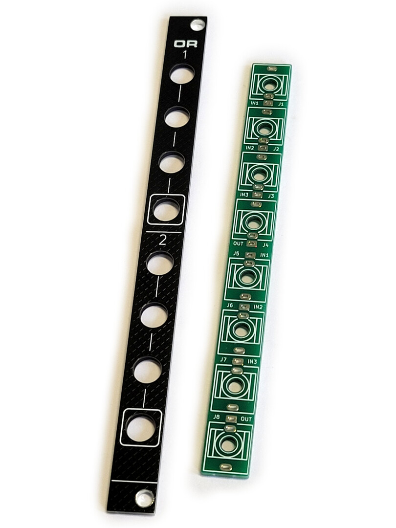
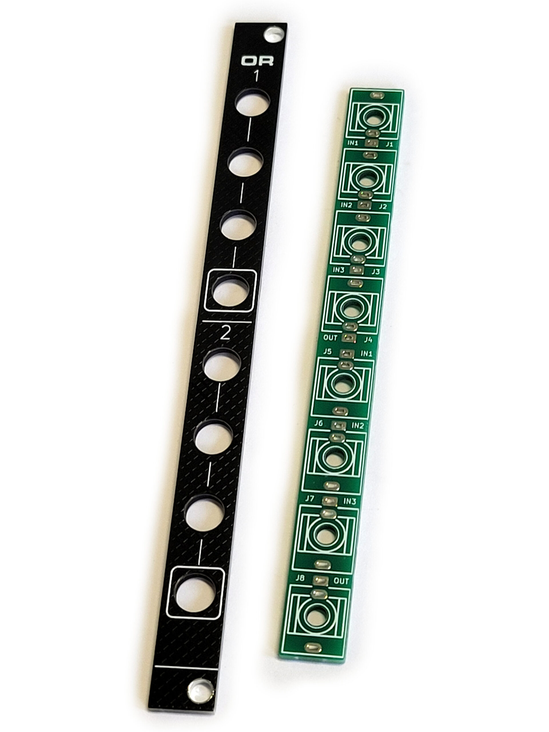
Assembly guide