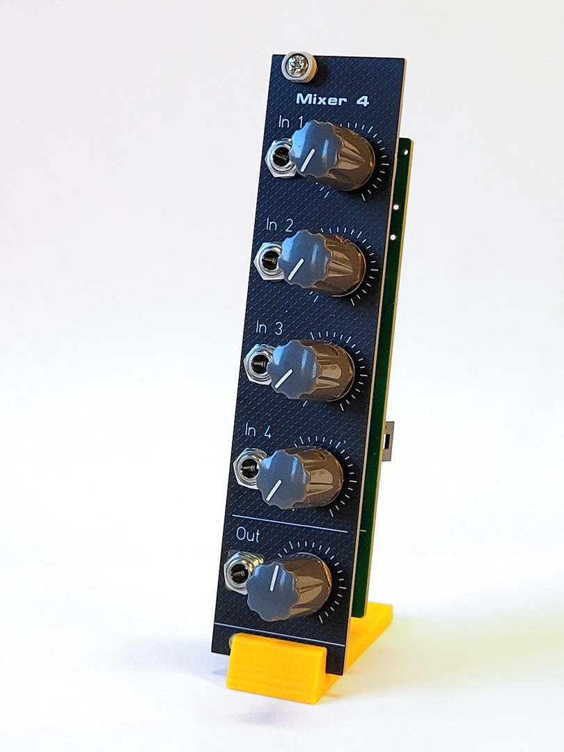
The Mixer 4 is a straightforward 4 AC-coupled mono input mixer for Eurorack systems.

Circuit description
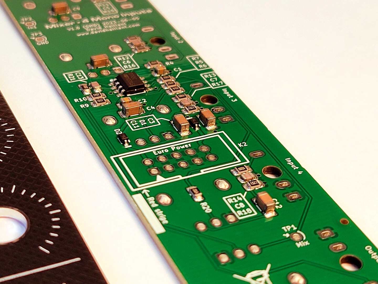
The circuit itself is very simple and has a relatively low component count.
There are only two op-amps in a single 8-pin package, U1.

The two op-amps are configured as inverting amplifiers.
More precisely, the first stage, U1B, is configured as a summing amplifier. It combines the four input signals, mixing, inverting and slightly attenuating them.
Each input has the exact same circuitry:
First, the signal passes through a low-pass filter to remove high-frequency noise, then though a low-pass filter to remove the DC component.
Then each signal is individually attenuated by a logarithmic potentiometer.
The output of the first op-amp stage is fed to the “master volume” logarithmic potentiometer, which can globally attenuate the mixed signals.
Finally, the mixed signal is inverted and amplified by the second op-amp stage (U1A) before being sent to the output jack.
This last stage includes a short-circuit protection resistor (R21), and its amplification gain is set by R10.
Components
All the components are SMT, except for the controls (potentiometers and jacks), and the Eurorack power connector.
- The potentiometers are Alpha-style, 9mm logarithmic potentiometers.
- The jack sockets are 3.5mm “Thonkicon” style.
Value changes
- R10 should be 47k (it was originally 22k). Note that if you’re satisfied with the current global gain of the mixer, there’s no need to replace the resistor. With a value of 22k, the global gain is approximately 0.47, meaning that a single signal will be attenuated at the output even if all potentiometers are set to maximum. Replacing R10 with a 47k resistor achieves a gain of 1, though this will, of course, saturate the output op‑amp more easily.
Assembly guide
Follow the step-by-step assembly guide for Mixer 4.
Gallery
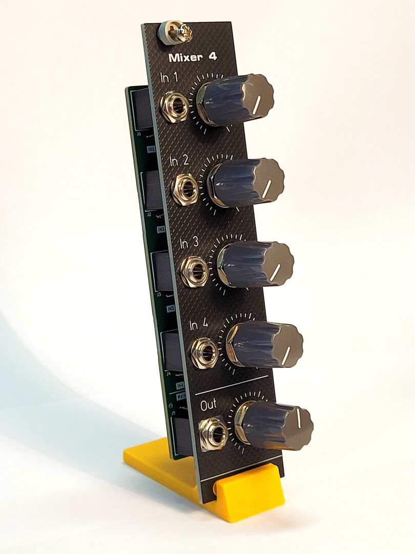
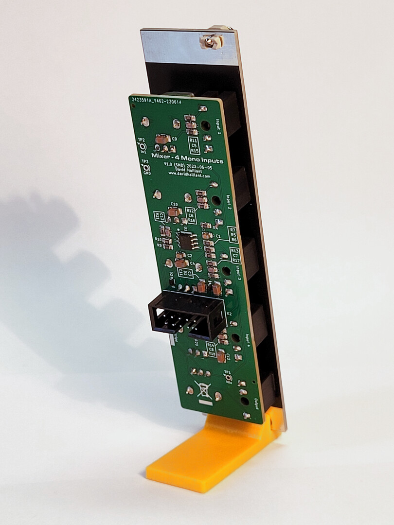
Front panel and PCB


Documentation and downloads
- Schematics (mixer-4-v1.0smd-20231123.pdf)
- Interactive BOM (Mixer – 4 Mono Inputs-1.0 (SMD)-ibom-2023-11-23)
