Step by step assembling guide for the Mini Dual Power Supply. Please read all the step at least once before starting assembling.
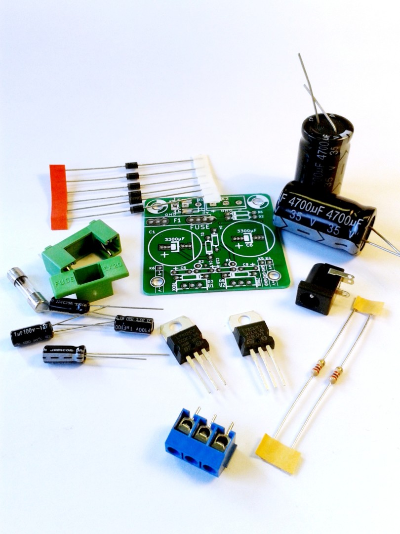
Mini Dual Power Supply requires very small amount of components
Bill Of Material:
An AC/AC adapter or a simple transformer (single secondary/ 2 wires). Do not use a DC plug pack.
1 x LM78xx (eg. 7812 for +12V) (U1)
1 x LM79xx (eg. 7912 for -12V) (U2)
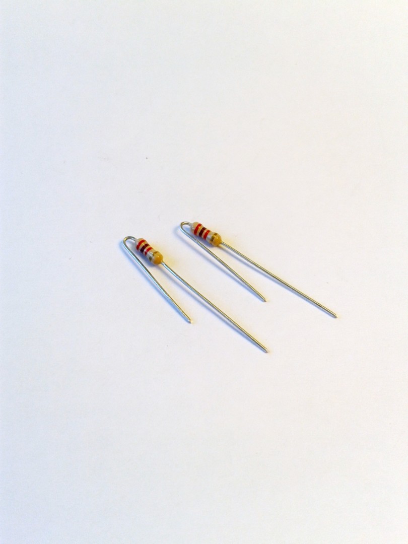
2 x 1/4 Watt 5% 2,7K resistors (R1, R2)
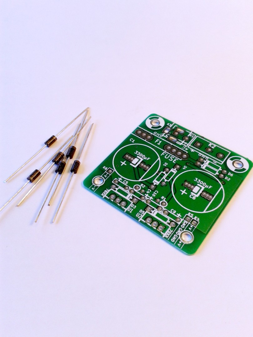
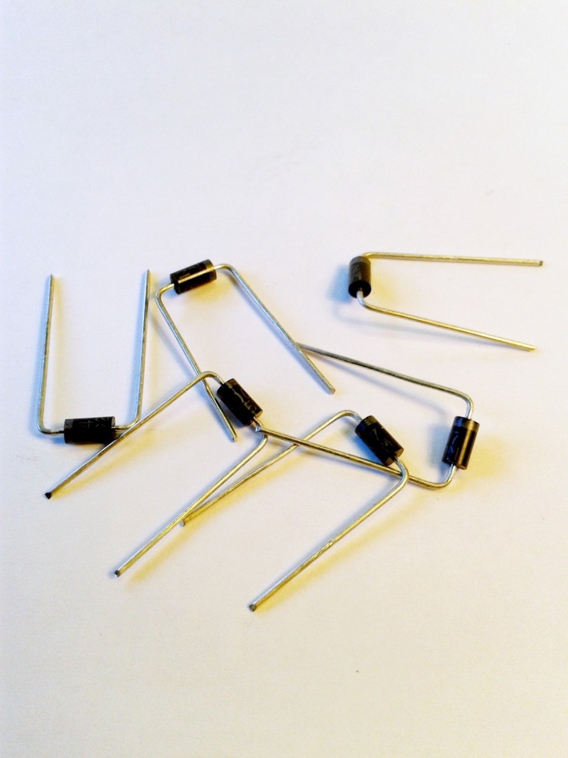
6 x 1N4007 diodes (D1, D2, D3, D4, D5, D6)
2 x 3300uF 35V capacitors or bigger (C1, C6)
4 x 1µF capacitors (C4, C5, C9, C10)
1 x fuse, fuse holder, connectors, etc.
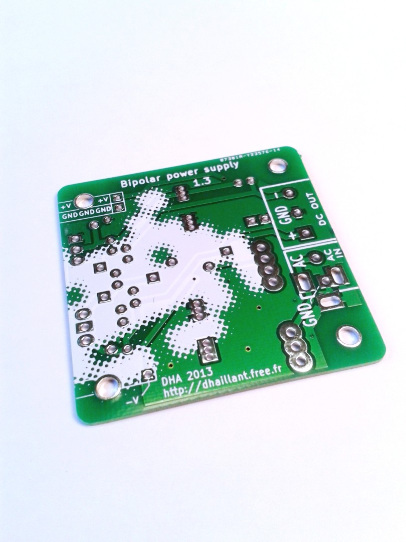
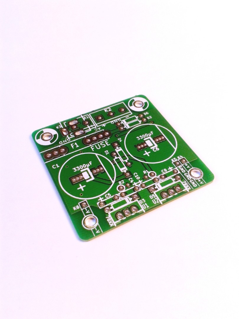
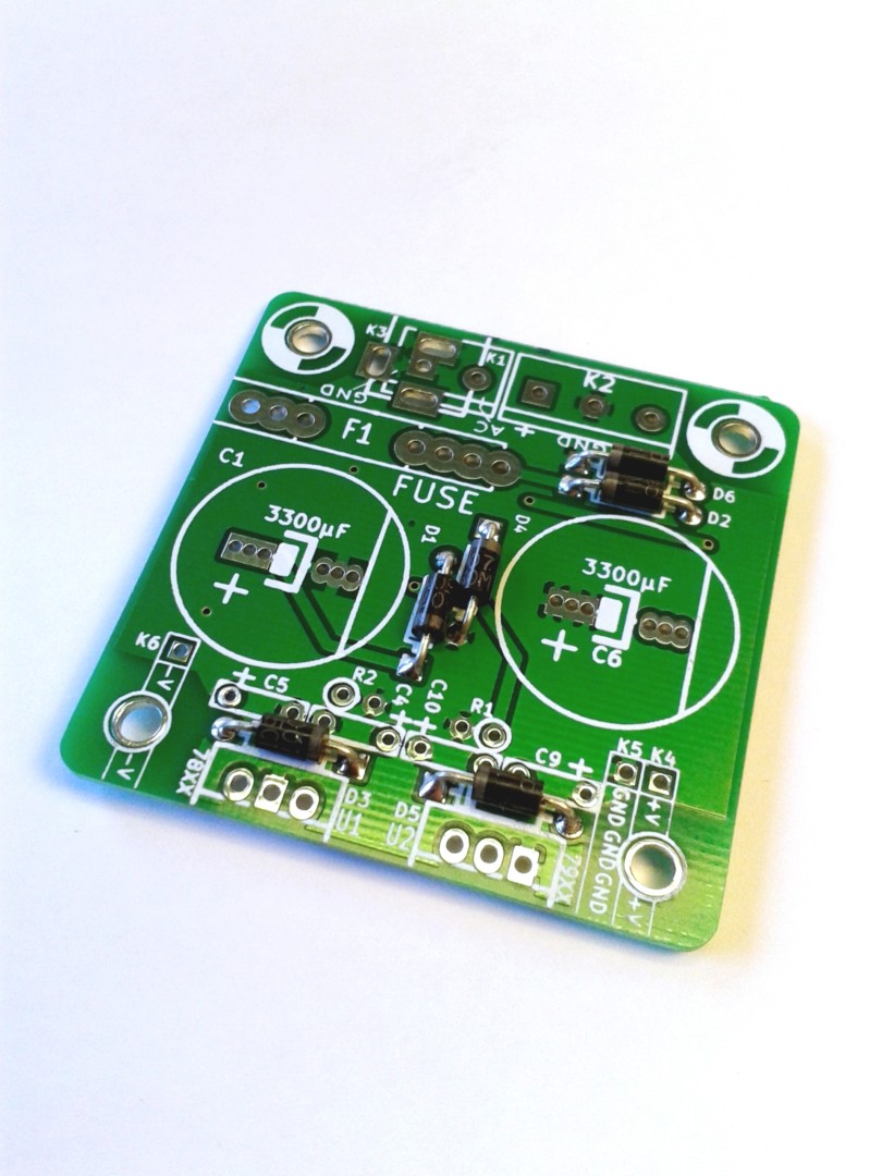
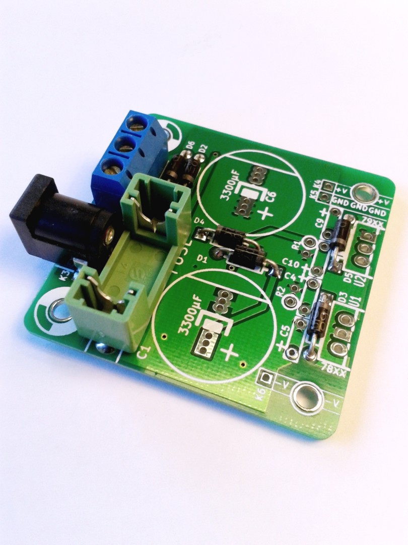
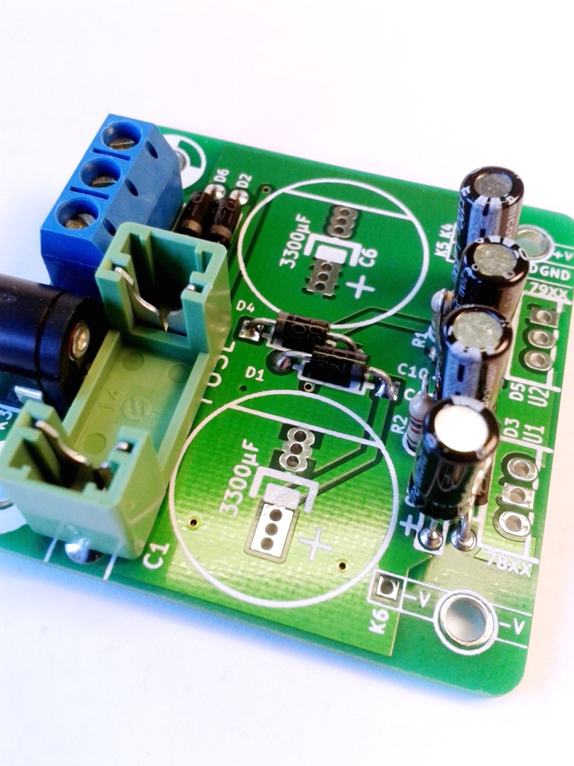
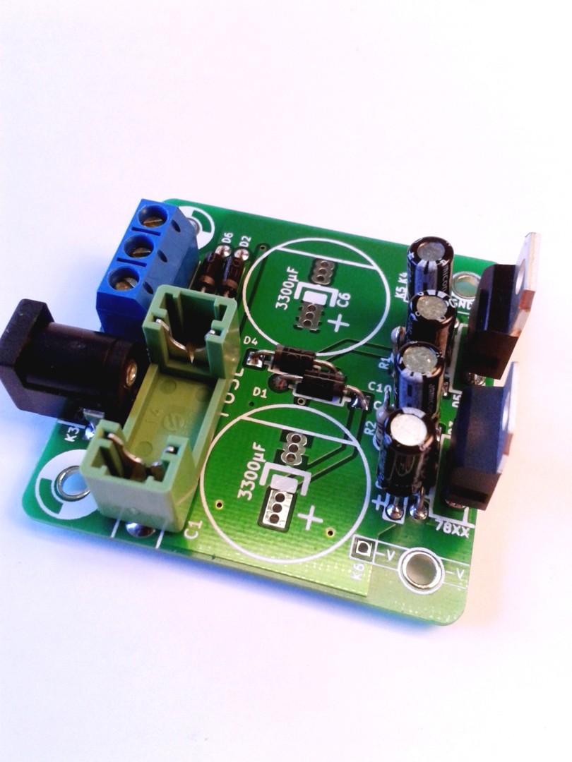
PCB Bottom Side Component Side
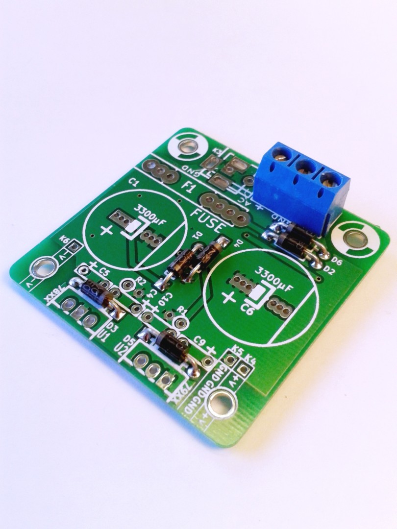
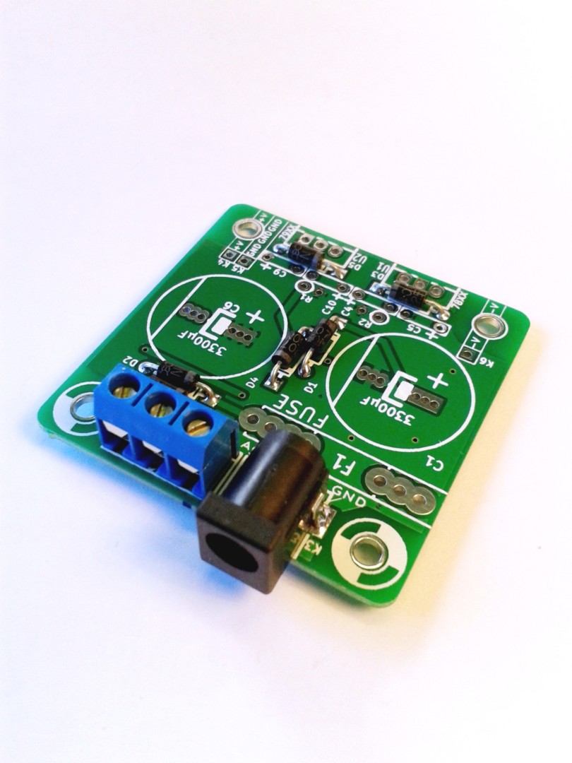
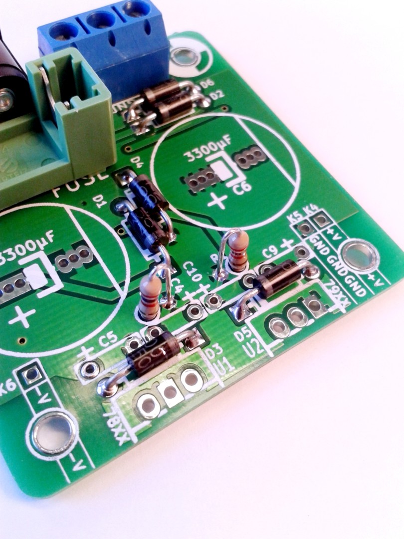
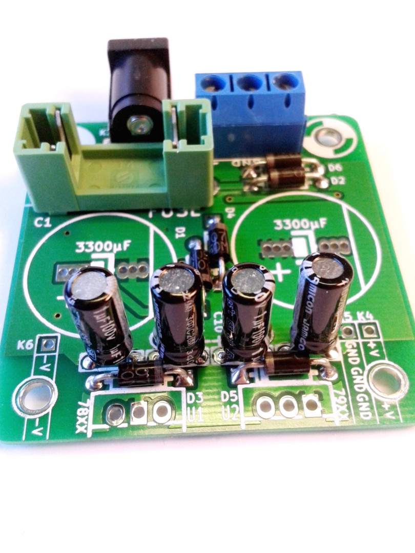
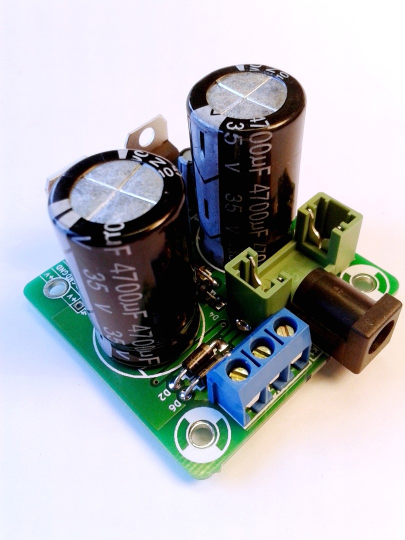
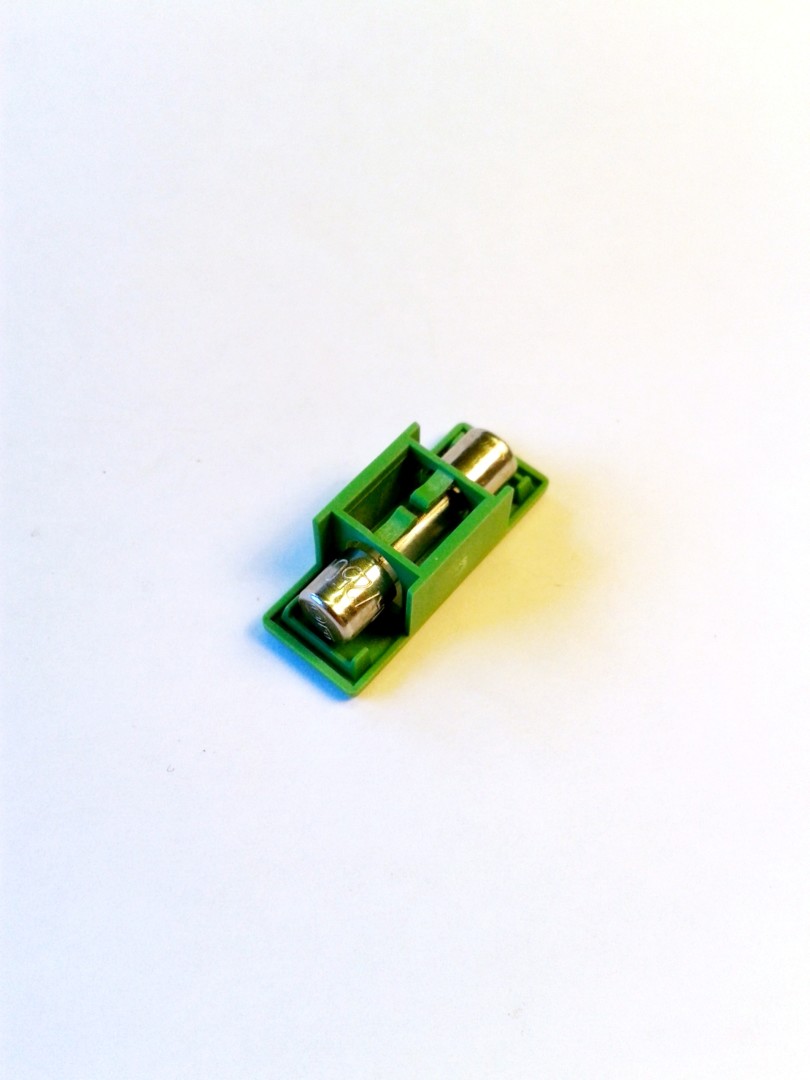
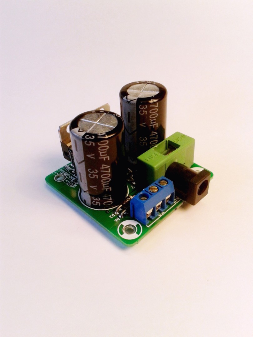
Start by assembling the 6 Diodes Bend the legs Be careful. You must respect the diodes polarity. Align the diode white ring and PCB’s white marks. D1 and D4, D3 and D5 are in opposite directions. D2 and D6 are in the same direction. Continue by soldering the screw terminal. Wire holes should face outwards. You can skip this component if you intend to solder wires directly to the PCB. Solder the AC Jack connector. Leave enough space for the fuse holder that will sit between the connector and capacitor C1. You might want to skip this component as well if you intend to use a panel mount connector instead. Solder the fuse holder. Bend the legs of the two resistors as shown. Solder the resistors. Place the four small capacitors C4, C5, C9 and C10. On PCB 1.3, the capacitors mark is rectangular. Capacitors are polarized. Plus side is showed on PCB with a “+” mark. On capacitors, the longest pin is the positive side. The white thick side band is the negative side. Another view of the small capacitors. They need to be away from the regulators: place them in order to let the maximum distance between them and the regulators. Place the two regulators. You must respect their orientation and their respective position. 78xx is U1 (foreground on the picture) and 79xx is U2 (background on the picture). As mentioned before, please ensure that the capacitors are not touching regulators bodies. Separate them as much as you can. Regulators must be vertical. Then, solder the two big capacitors C1 and C6. You must respect polarity. Longest pin is positive side. The side band shows negative side. Finish by inserting the fuse in the fuse holder cover and plug it into the fuse holder. Finished Mini Dual Power Supply.
4 thoughts on “Mini Dual Power Supply: Assembling it”
Bonjour. Comment on fait pour l’utiliser avec un flying bus? Je voudrais commander un si cela est possible. Merci
Jovan
Bonjour,
Avec un flying bus, il faudrait soit modifier le bus soit créer un adaptateur.
Modifier le bus, cela revient à couper le connecteur femelle d’extrémité et dénuder les fils correspondants au +12V, 0V et -12V, puis les brancher dans le bornier à vis.
Un adaptateur serait équipé d’un connecteur mâle d’un coté et de fils dénudés de l’autre.
Attention toutefois, l’alim ne délivre pas le +5V.
By using a 15v wallwart , and 7815/7915 is there anything else I would need to alter to get a + – 15 volt supply
With 7815/7915 and an adequate AC/AC adapter, you’re all set for +15/-15V power supply.