A friend gave me an old defective ITT MX20 Multimeter.
The multimeter is still currently sold under various brands. It’s a very rugged, IP66, electricity oriented multimeter.
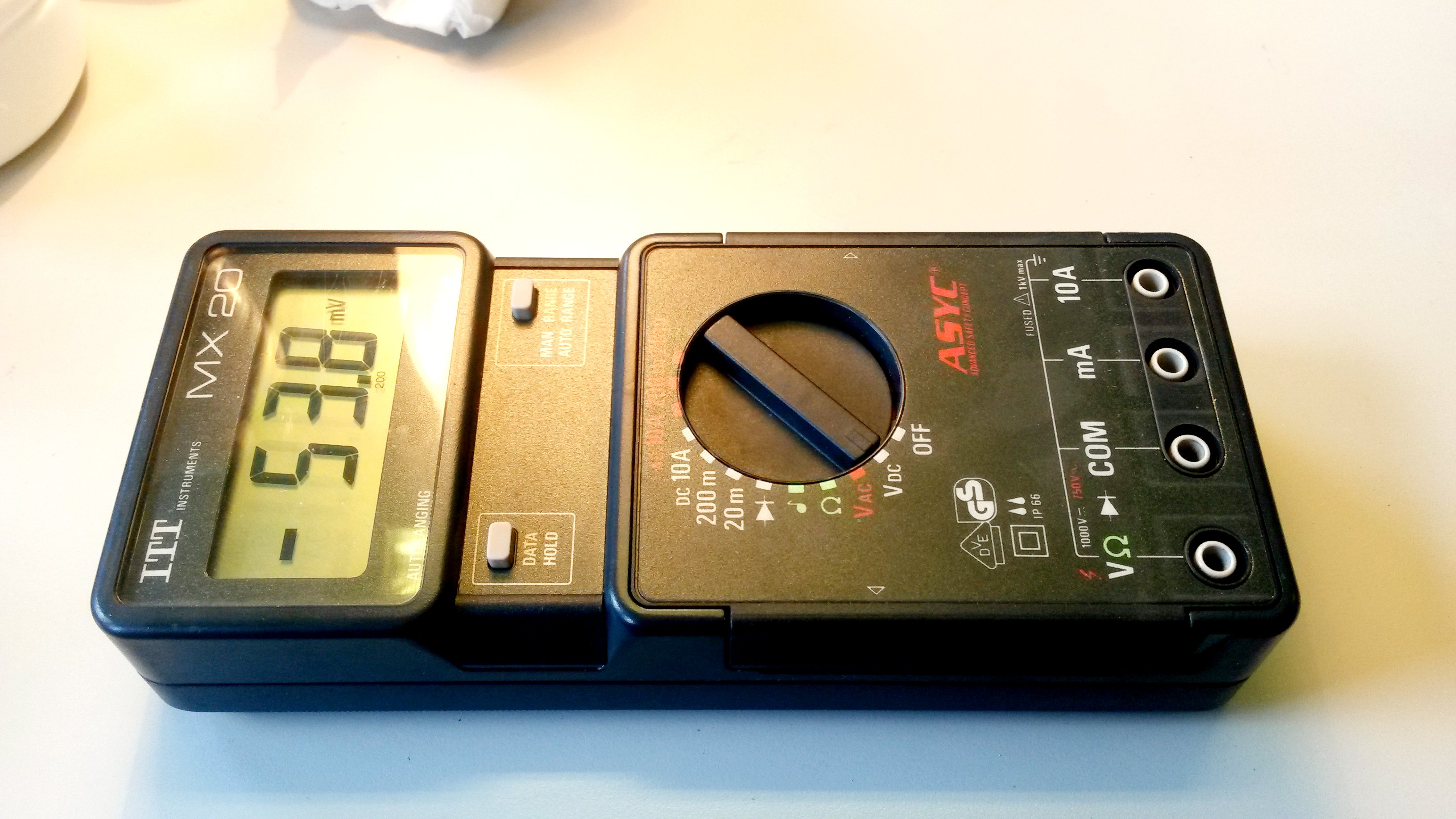
The multimeter, now in working order.
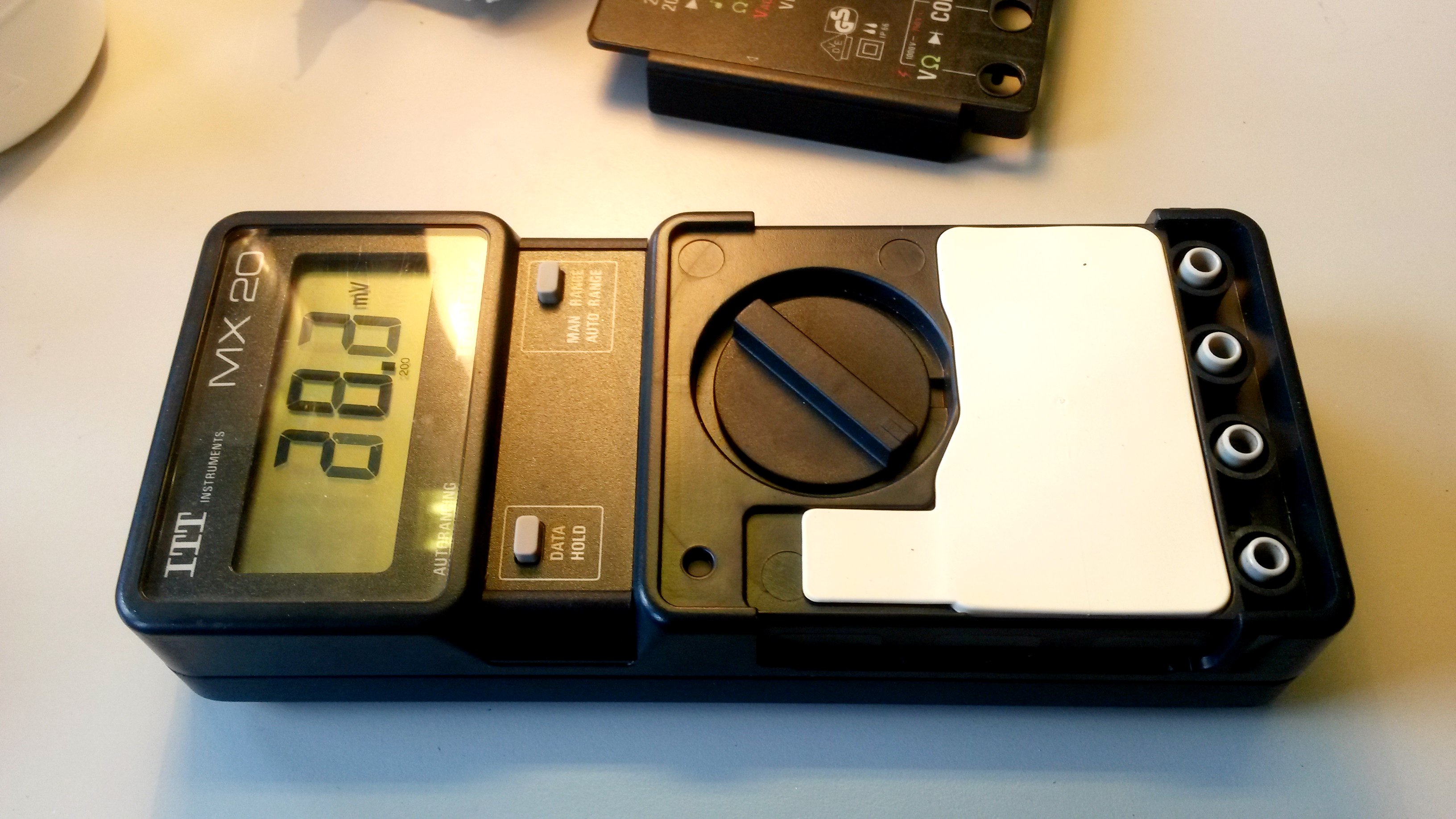
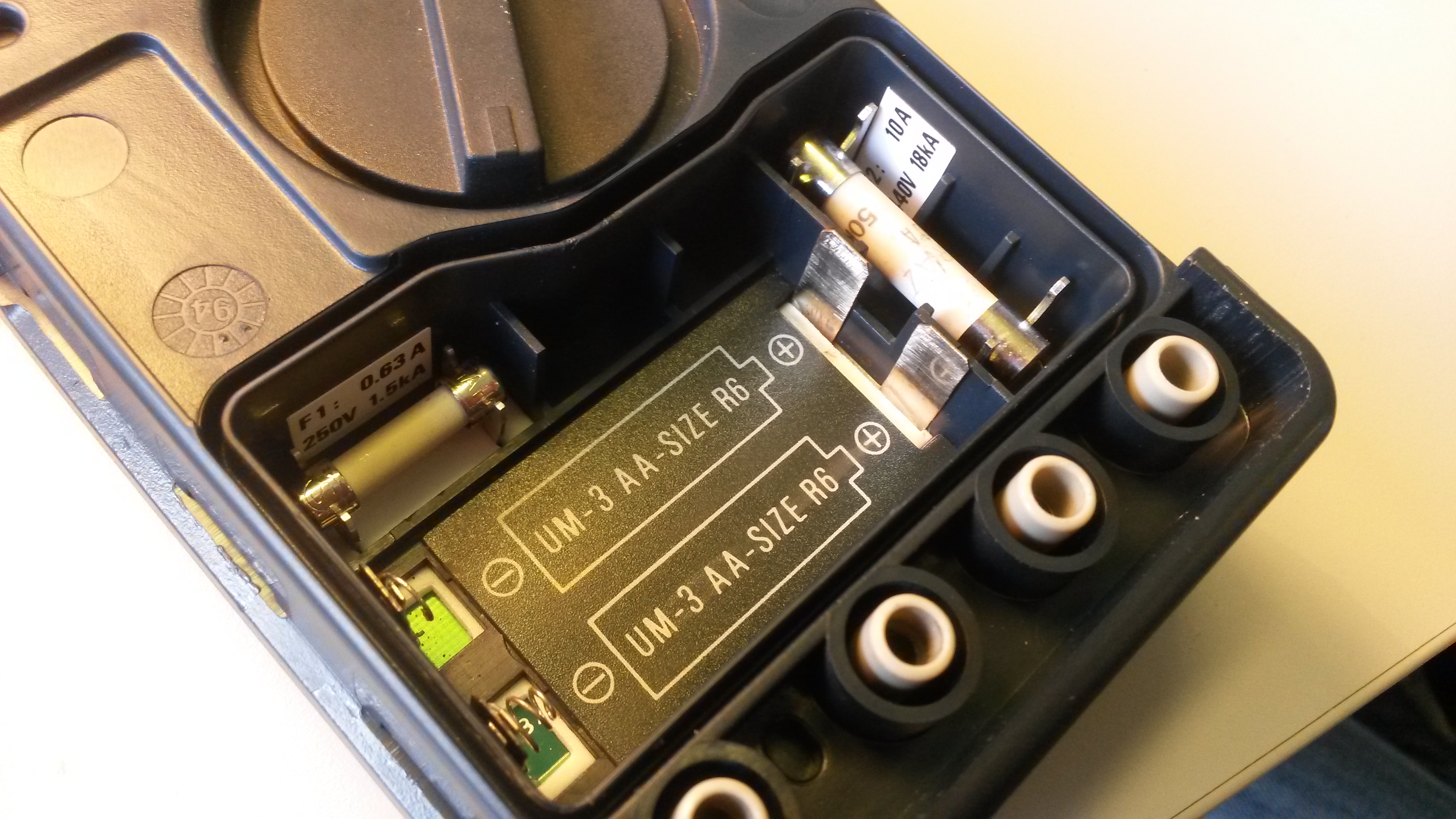
Removing the front panel reveals the IP66 rubber seals.Behind that seal, we find the two AA batteries and the two HRC fuses compartment.Finally, the rear panel is the way to open the meter. No screw here, it’s simply clipsed…
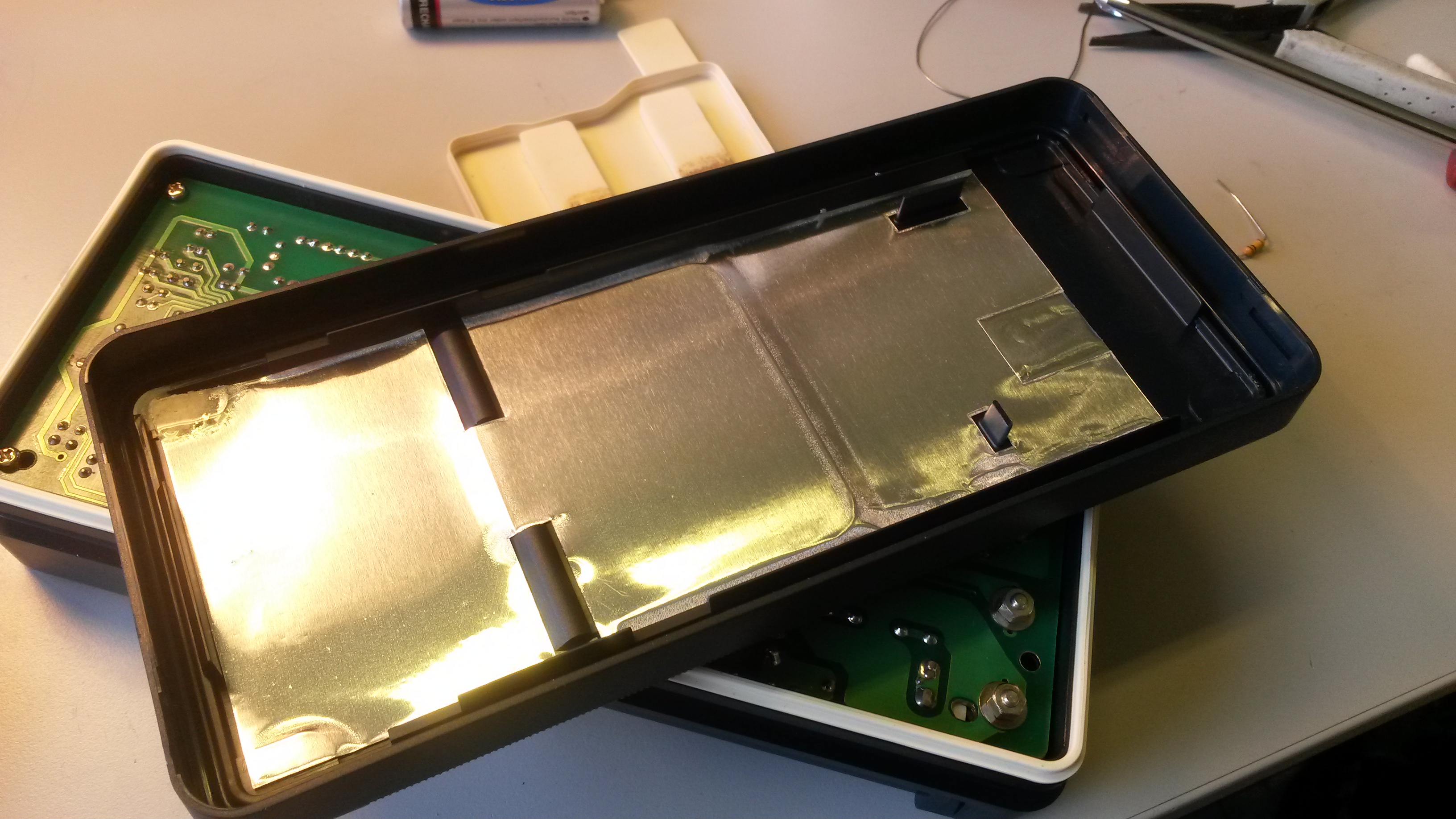
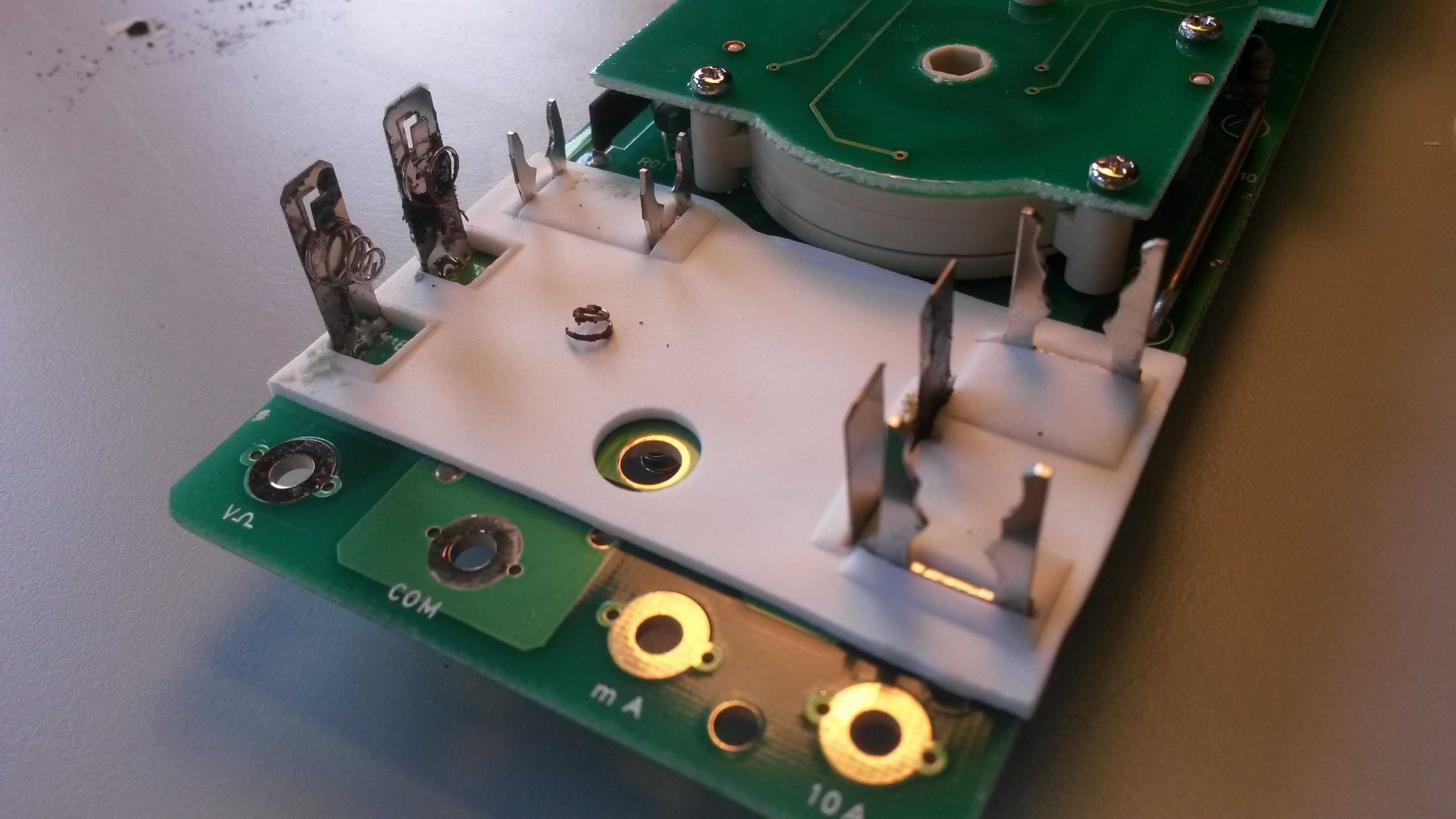
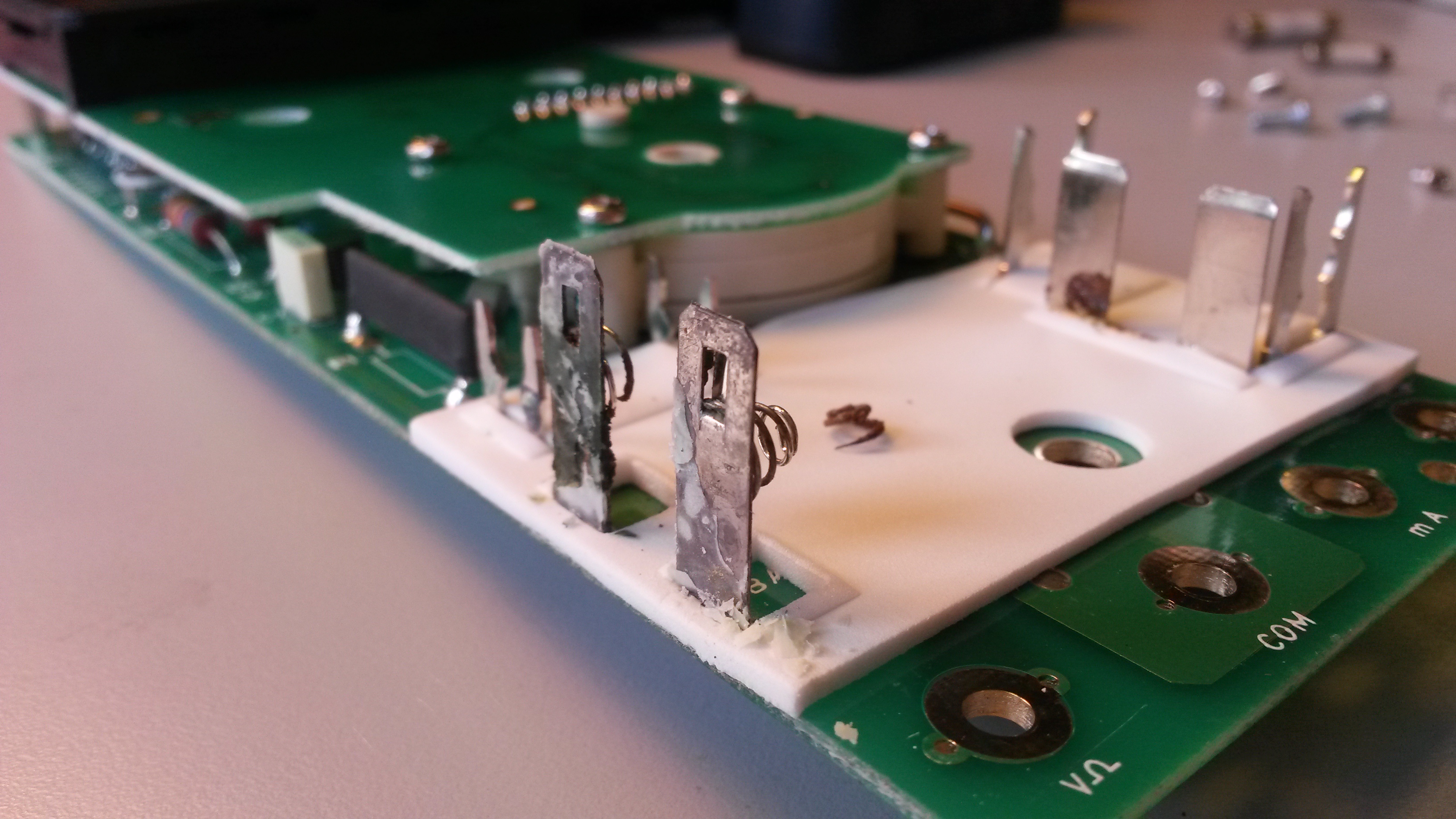
Notice the white rubber seal though.As you see in next pictures, the main problem in this meter was a leaky battery. Corrosion is present on the back cover shielding foil. No worries.Banana posts are directly bolted onto the PCB. Too bad, no shake proof washers. And fortunately, as the batteries are just behind, the PCB has no sign of corrosion.Nice and clean PCB layout.The corrosion from the leaky battery. One of the two springs is badly damaged.Corrosion on the other side.
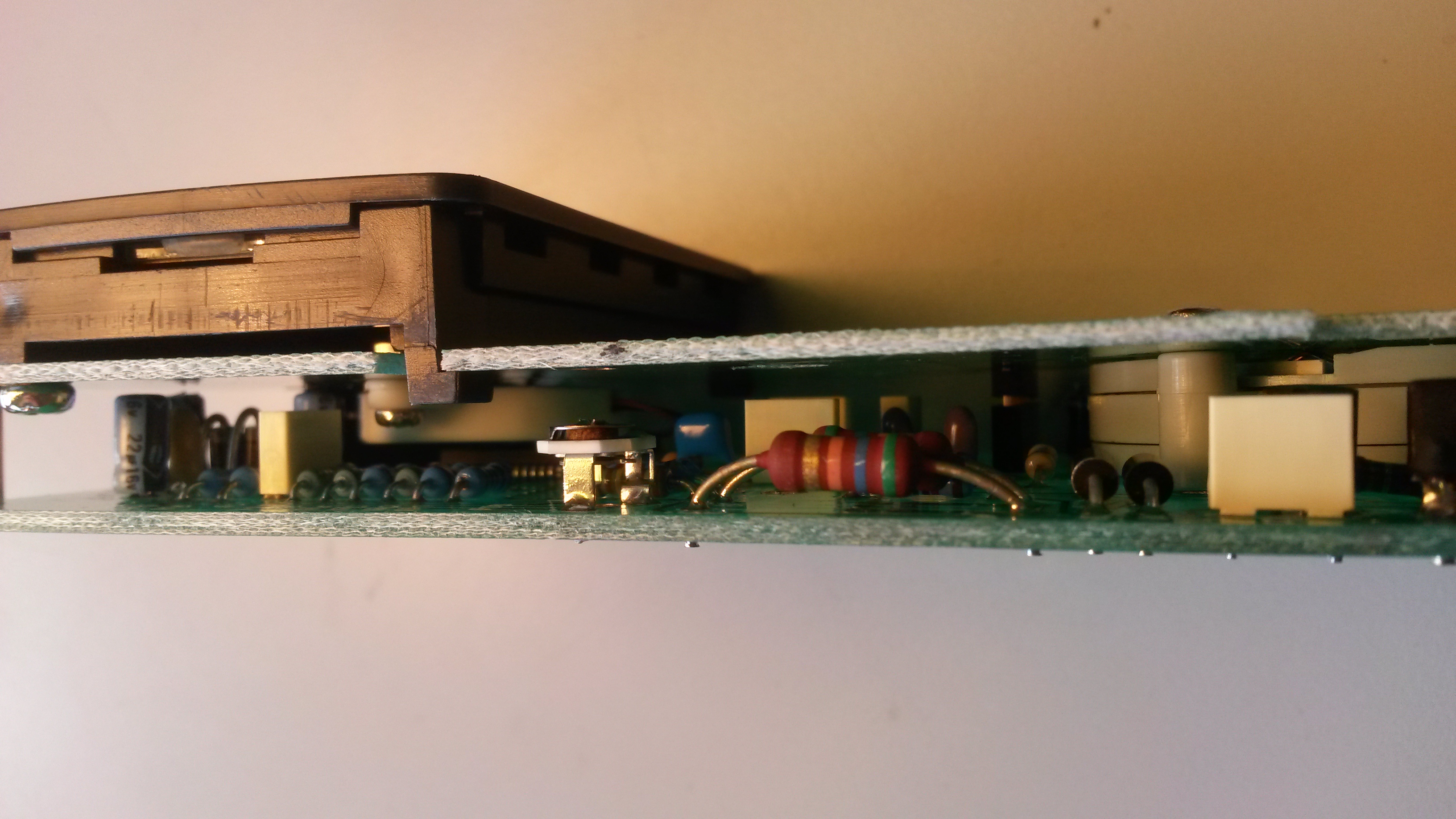
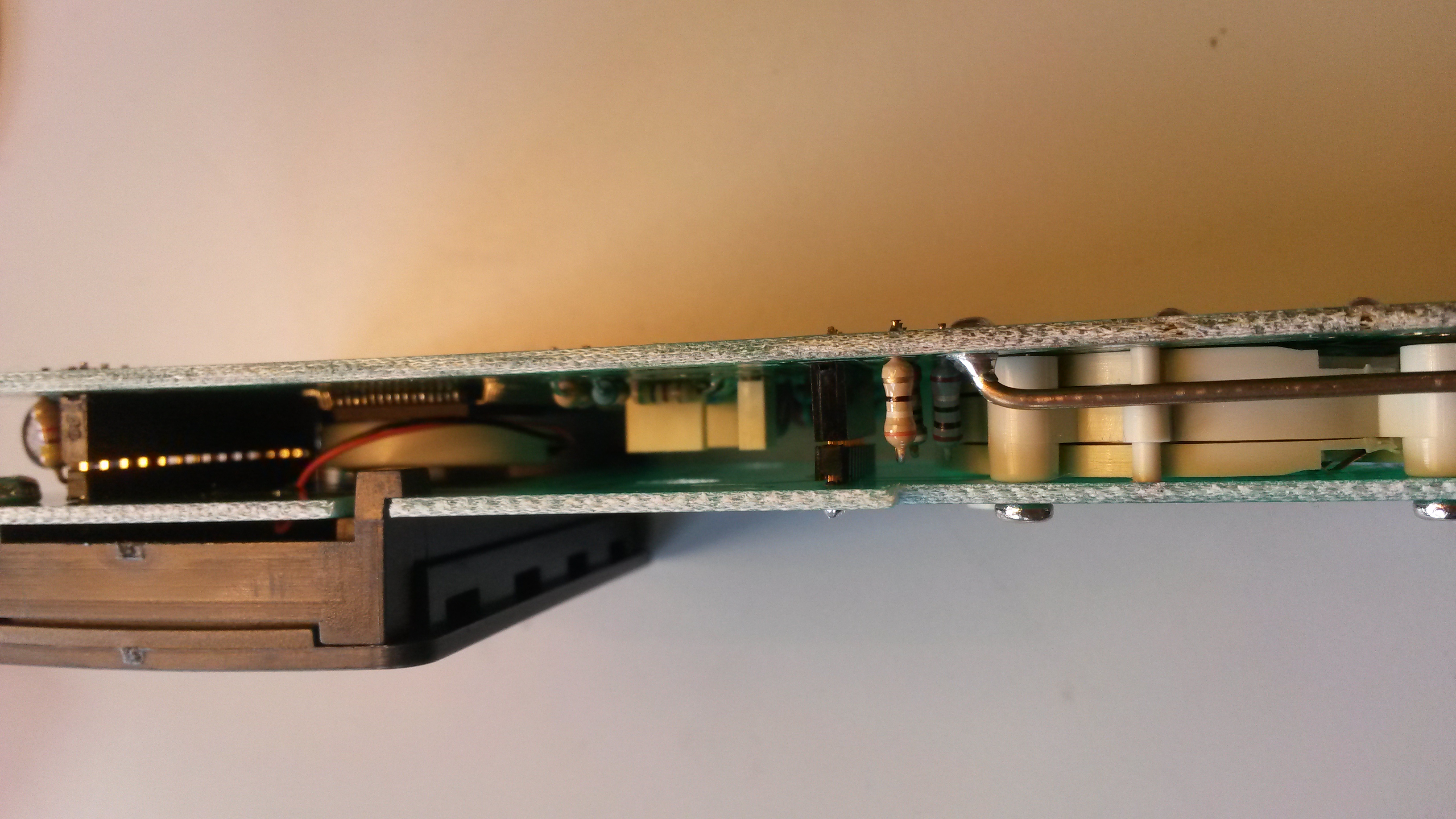
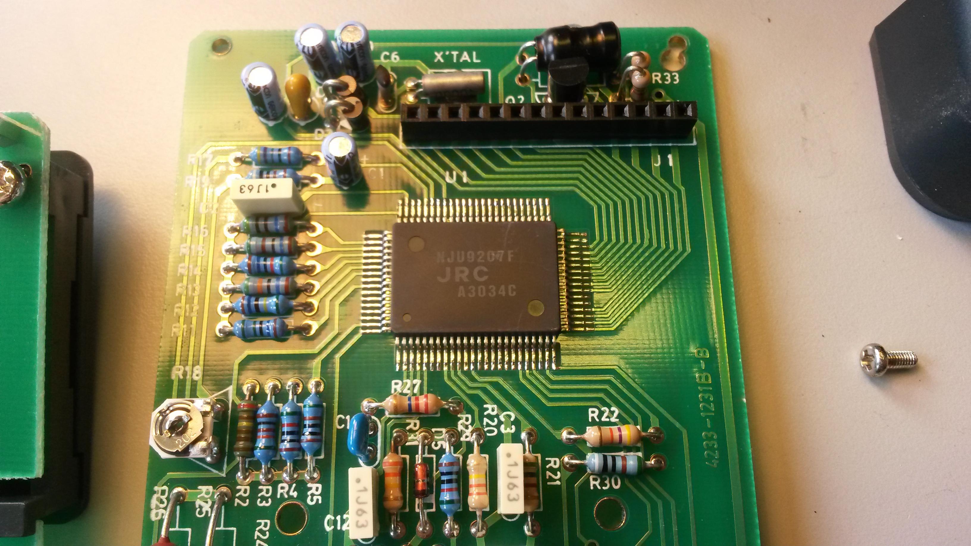
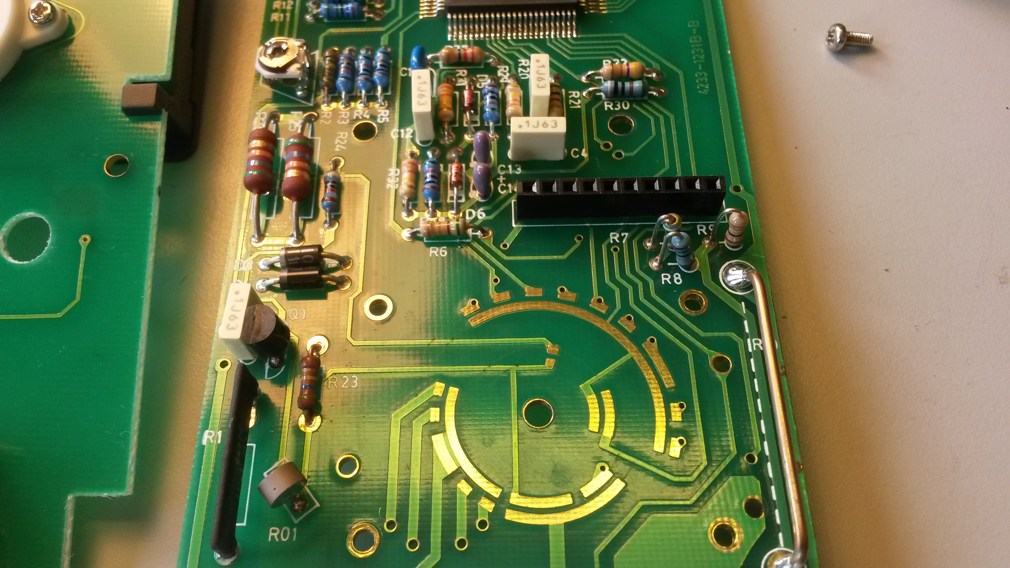
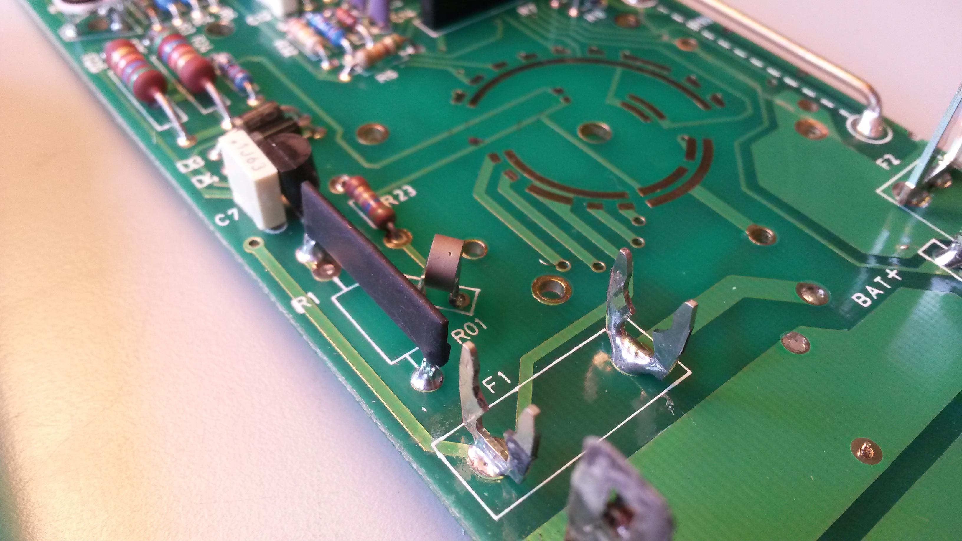
The MX20 is built in a dual PCB layout.The main board is on the back. It’s a mix between surface mount and through hole components.This side shows the current shunt resistor and the two PCB to PCB interconnect system. Two simple 2.54 mm header connectors. They doesn’t fit completely inside…The two boards disassembled. Piezo buzzer sits under the LCD screen, close to the main chip. Just one big chip and a couple of passive components.A closeup on the main chip. It drives directly the LCD screen.And a closeup on the main switch contacts. On the left the input resistance for the voltmeter. On the left, the current shunt resistor for the amp meter.And finally a closeup on the… input protection. I’m not an expert, but it seems there’s no MOV, no diode bridge… I don’t know what’s R01…The battery compartiment, cleaned. Corrosion removed. Luckily the damaged spring doesn’t prevent good contact from the battery.
5 thoughts on “ITT MX20 Multimeter Teardown and refurbishment”
Hello
Fine photos you have!
There is a trimpot on the main PCB.
Do you the function of the trimmer?
Best regards
/Lars G
Stockholm


Hello
Fine photos you have!
There is a trimpot on the main PCB.
Do you the function of the trimmer?
Best regards
/Lars G
Stockholm
Hello Lars, sorry but I have no idea what this trimpot is for…
Hi, this is the calibration trimmer, the voltage indicated will vary slightly when you turn it. Regards
Hi
Do you have a picture of the PCB around the batterie container ?
This will help me to see if my PCB is damaged
Thanks
Tourterel (France)
Hi, I don’t have much pictures available. Maybe this one shows the region a bit more? https://www.davidhaillant.com/l/uploads/medium/b71b58628f7bb1488ba10f0c5c987b71.jpg
Let me know if you need a different view, I’ll check in my archives.
David