I made some scope measurements to help understand and debug faulty MFOS SLMS in SMT version.
My scope is not very accurate and the tested unit is far from perfect, but at least, it gives a pretty good idea of expected signals on the Test Points.
VCO1
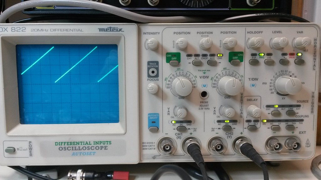
First signal to check is VCO1 (TP201). Put VCO1 Frequency pot in middle position (50%), LFO and AR switches on Off position:
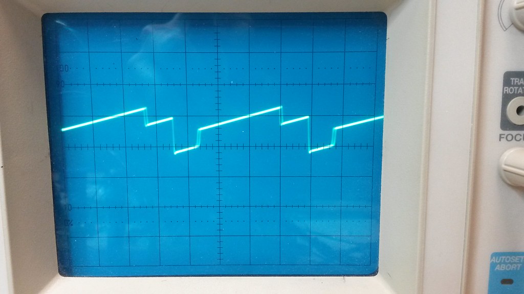
VCO2
Second signal is VCO2. Test point TP202. Set VCO2 at 50%, Sync, LFO and AR switches on Off position. Ramp/Rect switch on Ramp (see required mod for version 1.0)
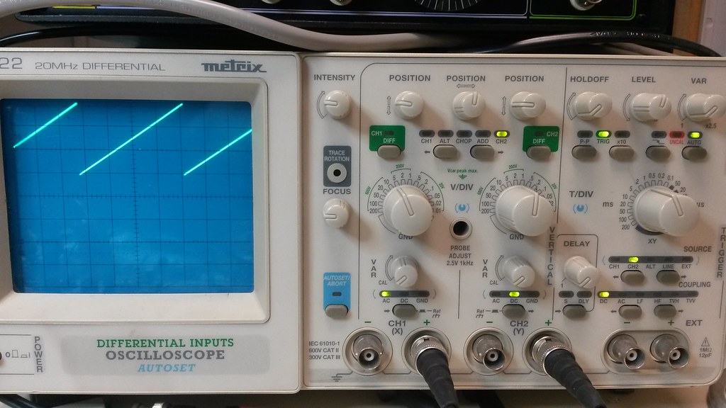
I’m not sure why VCO2 Sawtooth signal is from 1V to 4V instead of 0 to 4V like VCO1. It’s probably either the FET transistor “quality” or the PWM circuitry interfering somewhere…
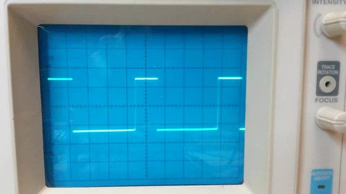
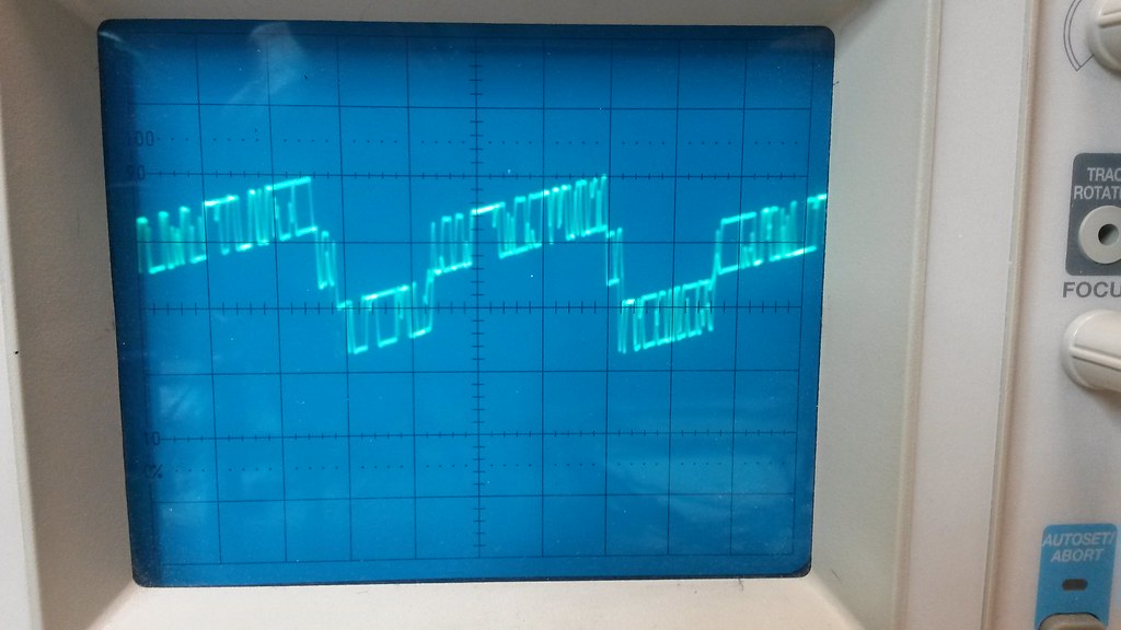
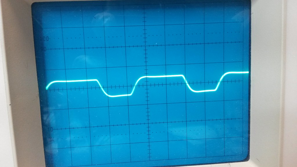
Now we check VCO2 in Rect position. PWM pot is set at 50% and S15 (PWM) switch is on Off position.
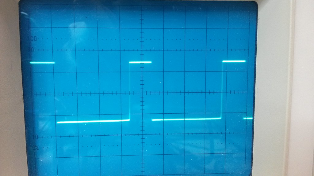
Modifying PWM pot position must modify the High/Low ratio.
Setting PWM switch ON allows LFO to modify the High/Low ratio.
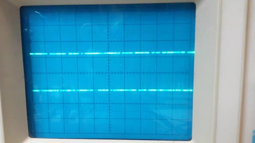
Noise
Noise signal quality and level vary greatly between Transistors.
SLMS noise stage has a high amplification gain, so Noise signal is pretty saturated.
The following signal can be seen on TP401 (Noise):
LFO
Put LFO Range Switch (S17) on “Low” position. Set Freq pot (R90) at 50%, Level pot (R92) at 100%.
Pick LFO signal at Test Point TP301.
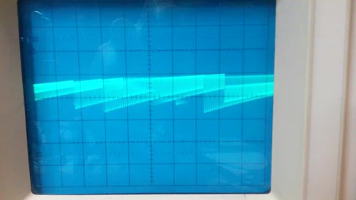
Set Ramp/Rect switch (S18) on “Ramps”. Set S16 (“Wave”) on “Ramp” (Upper position).
TBD
Set Ramp/Rect switch (S18) on “Ramps”. Set S16 (“Wave”) on “Tri” (Middle position).
TBD
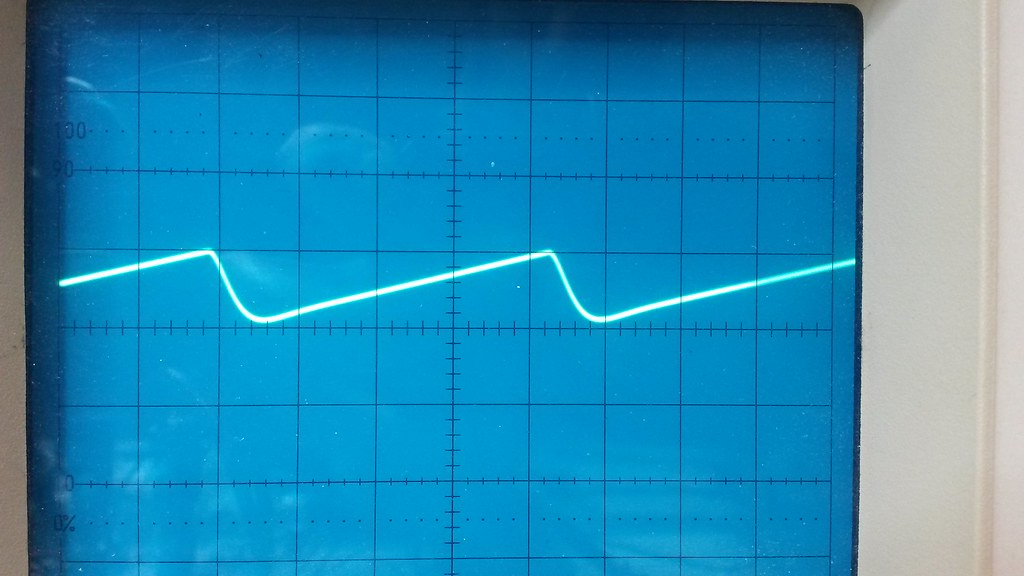
Set Ramp/Rect switch (S18) on “Ramps”. Set S16 (“Wave”) on “Sawtooth” (Lower position).
TBD
LFO “Ramps” signal is approximately 9V peak to peak, centered around 0V.
TBD
Set Ramp/Rect switch (S18) on “Rect”. Set S16 (“Wave”) on “Tri” (Middle position).
LFO “Rect” signal is 15V peak to peak, centered around 0V.
TBD
AR
TBD
LP
VCF is the first stage where the two VCO and Noise are mixed together.
First, set Cutoff pot position to “High” (100% clockwise) and Resonance pot down to 0%. Set all switches in VCF section to Off.
To get the following signal on Test Point “LP” (TP802), Set VCO2 on Rect waveform, turn VCO1 and VCO2 mixer pots to 100%, Noise mixer pot to 0%.
Levels, here, are approximately between -0.5V and 1.8V.
The signal shown below is identical but with Noise mixer pot at 100%.
Now set Cutoff pot to around 50% and use only VCO1 (VCO2 and Noise mixer pots at 0%).
Same settings, but with VCO2 mixer pot set at 100% and S10 on “Rect” position (VCO1 at 0%):
With Cutoff set at Lowest Frequency (0% / counter clockwise) I get a DC voltage of -4V on TP802. Slightly turning Cutoff pot to 5-10% clockwise, I get DC value of 0V.
With Cutoff at high freq (fully clockwise) and Resonance at 100%, self oscillation should occur, high pitched, on top of VCO signal:
BP
TBD