
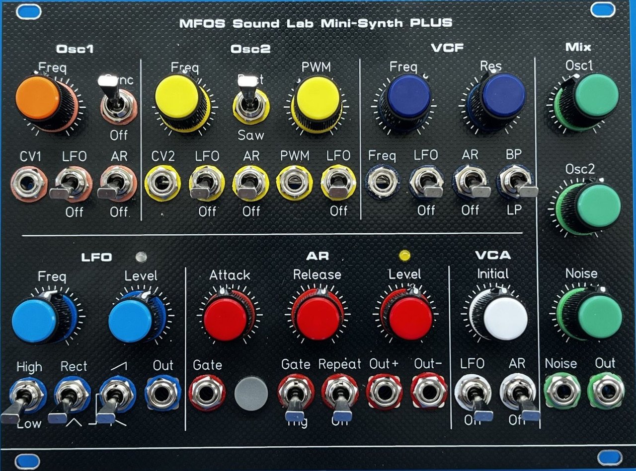
The MFOS Sound Lab Mini-Synth PLUS (SMD version) is an Eurorack adaptation of Ray Wilson’s classic Sound Lab Mini-Synth PLUS, itself a substantially enhanced evolution of the original Sound Lab Mini-Synth (SLMS). This conversion is part of the official effort by SynthCube to bring the Music From Outer Space (MFOS) analog synthesizer designs into the Eurorack modular format.
Overview
This module is the direct successor to the SLMS SMD Eurorack project. It shares the same design philosophy: surface mount construction, fully PCB-integrated layout, no off-board wiring, while introducing the expanded feature set of the PLUS design alongside several original modifications specific to this version.
Ray Wilson’s Sound Lab Mini-Synth was one of the most popular DIY synthesizer projects ever published on the Music From Outer Space website. The PLUS was his own enhanced reprise of that original design, with circuit topology improvements, revised component values, and additional modulation capabilities. This SMD Eurorack adaptation translates the PLUS circuit to the Eurorack standard: ±12V power rail, 3.5mm jacks, compact panel format, with a number of additional modifications detailed below.
Signal Path Architecture
The SLMS PLUS SMD follows a classic subtractive synthesis architecture:

Functional Blocks
Voltage Controlled Oscillators (VCO 1 & VCO 2)
The synthesizer features two independent, musically accurate VCOs, each tracking at 1V/octave. Tracking accuracy across five octaves is achieved by means of dedicated high-frequency correction trimmers on each oscillator.
A stable, dedicated on-board voltage reference is used for all critical circuits in place of the power supply rails.
VCO 1:
- Waveform: sawtooth
- Hard sync input (receiving from VCO 2)
- LFO pitch modulation switch
- AR pitch modulation switch
- CV input: CV1 (1V/oct, main pitch CV)
VCO 2:
- Waveforms: sawtooth and pulse (Rect), selectable via front-panel switch
- Variable pulse width (PWM): a dedicated potentiometer sets the base duty cycle offset; the PWM can be further modulated by the LFO via a dedicated switch
- Hard sync output (driving VCO 1); sync enabled via front-panel switch
- LFO pitch modulation switch
- AR pitch modulation switch
- CV input: CV2 (1V/oct)
- CV1→CV2 normalling jumper: when no jack is inserted into CV2, a solder jumper on the PCB routes CV1 to CV2 (position ON), or connects CV2 to ground (position OFF). Inserting a jack into CV2 always overrides the jumper setting.
Both oscillators share the same expo converter architecture, temperature-compensated and trimmed for accurate tracking.
Noise Source
A white noise generator feeds the signal mixer alongside the two VCOs, with its own independent level control. The noise source is also available as a dedicated auxiliary output on the panel (see Auxiliary Outputs section).
Signal Mixer
The mixer section provides individual level controls for:
- VCO 1 output
- VCO 2 output
- White noise source
The summed signal feeds the voltage controlled filter (VCF).
Voltage Controlled Filter (VCF)
The VCF is a 2-pole (12 dB/octave) state-variable filter with two operating modes, selectable via a front-panel switch:
- Low-pass (LP)
- Band-pass (BP)
The filter features:
- Cutoff frequency control (manual knob)
- Resonance control: the filter can self-oscillate at maximum resonance
- CV input for cutoff modulation (not present on the original SLMS)
- LFO modulation switch for filter cutoff
- AR modulation switch for filter cutoff
Voltage Controlled Amplifier (VCA)
A linear VCA follows the filter in the signal chain. Its gain is controlled by a Initial potentiometer, and two modulation sources, each independently activated by a front-panel switch:
- LFO modulation switch
- AR modulation switch
There is no dedicated external CV input for the VCA. The audio output is at standard Eurorack levels.
AR Envelope Generator
The AR envelope generator provides modulation across four destinations, each independently activated by a front-panel switch. A single AR Level potentiometer sets the modulation depth globally for all active destinations.
Controls and inputs:
- Attack time: adjustable from a few milliseconds to several seconds
- Release/Decay time: adjustable from a few milliseconds to several seconds
- Gate input: accepts a standard Eurorack gate signal
- Manual trigger button: triggers the envelope independently of an external gate source
- Gate / Trig switch: selects the envelope operating mode:
- Gate mode: the envelope sustains at peak level for the duration of the gate signal, then falls (AR behavior)
- Trig mode: the envelope rises to peak then immediately falls, regardless of gate length (AD behavior)
- Repeat switch (Trig mode only): when active, the envelope cycles continuously, functioning as an additional low-frequency oscillator or auto-trigger source
Modulation destinations (each with independent front-panel switch):
- AR → VCO 1 pitch
- AR → VCO 2 pitch
- AR → VCF cutoff
- AR → VCA
Two auxiliary AR outputs are available on the panel (see Auxiliary Outputs section), with jumper S201 selecting pre- or post-attenuation signal level.
Low Frequency Oscillator (LFO)
The LFO provides cyclic modulation with four available waveforms and a global LFO Level potentiometer that sets the modulation depth for all active destinations simultaneously.
Waveform selection:
- High / Low switch: selects between two frequency ranges, extending the LFO’s usable span from very slow modulation to near audio-rate
- Rect / Ramps switch: selects between the square wave (Rect) and the ramp waveform family (Tri, Ramp, Saw)
- Ramp waveform switch (active in Ramps mode): selects among triangle (Tri), ramp up (Ramp), and ramp down (Saw)
Unlike the original SLMS, where obtaining a clean Rect output required the ramp shape switch to be set to the Tri position first, the PLUS design fully decouples the two selections: Rect is available regardless of the ramp shape switch position.
Modulation destinations (each with independent front-panel switch):
- LFO → VCO 1 pitch
- LFO → VCO 2 pitch
- LFO → VCO 2 PWM
- LFO → VCF cutoff
- LFO → VCA (tremolo)
An auxiliary LFO output is available on the panel (see Auxiliary Outputs section), with jumper S301 selecting pre- or post-attenuation signal level.
Auxiliary Outputs
A set of dedicated auxiliary output jacks exposes internal signals for use elsewhere in a patch. These outputs are not present in the original MFOS PLUS design and significantly expand the module’s integration with the broader Eurorack ecosystem.
| Jack | Signal | Notes |
|---|---|---|
| AR Out+ | AR envelope | Positive-going envelope |
| AR Out− | Inverted AR envelope | Algebraic inverse of Out+; amplitude always equal and opposite |
| LFO | LFO output | Waveform as selected by front-panel switches |
| Noise | White noise | Unfiltered broadband noise |
Jumper settings
Pre / Post attenuation jumpers
S201 (AR outputs): selects the signal level fed to both Out+ and Out− jack connectors. In the Pre position, both outputs carry the raw AR envelope signal, independent of the front-panel AR Level potentiometer. In the Post position, the attenuated signal, as set by the AR Level knob, is used instead. Out− is always the algebraic inverse of Out+, regardless of jumper position.
S301 (LFO output): selects the signal level fed to LFO output. In the Pre position, the output carries the full-amplitude LFO signal before any attenuation. In the Post position, the output mirrors the attenuated LFO level as applied to the internal modulation buses.
These options allow the module to serve simultaneously as a synthesizer voice and as a modulation source for other modules, with independent control over output levels.
CV2 normalling
S303 (CV2 normalling CV1 / GND) Controls the behavior of the CV2 input (J3) when no jack is inserted. In the ON position, CV1 is normalled through to CV2, so both VCOs track the same pitch CV without requiring an external mult or patch cable. In the OFF position, the CV2 input is connected to ground, leaving VCO 2 free-running at its manually set frequency. As with any normalized jack, inserting a plug into J3 overrides the jumper setting and routes the incoming signal to VCO 2 regardless of S303’s position.
The PCB


Those beautiful colored washers and big toggles!!